
Microfluidic device and its use for positioning of cells or organisms

a microfluidic device and positioning technology, which is applied in the field of microfluidic devices and its use for positioning cells or organisms, can solve the problems of difficult to maintain a hemostasis with stable temperature and humidity, labor-intensive conventional methods, and poor integration of microdevices

Active Publication Date: 2014-01-02
CAPITALBIO CORP +1
View PDF1 Cites 9 Cited by
  • Summary
  • Abstract
  • Description
  • Claims
  • Application Information

AI Technical Summary

Benefits of technology

The microfluidic device described in this patent has several advantages: it can hold different types of cells or organisms, track specific ones, and provide a flexible and flexible design for a wide range of applications. It uses microchannels and a positioning well for easy handling and monitoring of cell or organism conditions. It can also be integrated with optical detection devices and used for in situ detection. Additionally, it reduces the consumption of reagents and samples, and can be sterilized and sealed to prevent pollution and damage. The device is easy to fabricate, cost-effective, and reusable.

Problems solved by technology

However, a microdevice integrating all aforementioned steps is yet to be developed.
Since all the steps are conducted in Petri dish or tubes except oocyte collection, it's difficult to maintain a hemostasis with stable temperature and humidity.
Besides, the conventional method is labor-intensive and poorly integrated.
However, this device failed to select a single embryo out of a group, and it's not convenient for positioning and retrieval when dealing with more than one embryo.
Moreover, shear force can hardly be avoided due to the constriction structure.
However, the communication between the cells in adjacent wells is highly limited without gaps between the wells and it's difficult to build up of beneficial auto / paracrine factors from cell-cell contact or cell-environment crosstalk.

Method used


Image

  • Microfluidic device and its use for positioning of cells or organisms
  • Microfluidic device and its use for positioning of cells or organisms
  • Microfluidic device and its use for positioning of cells or organisms

Examples


example 2

Microfluidic Chips

[0060]As shown in FIG. 8, the difference between this exemplary embodiment and Example 1 lies in: there is one basal layer 7 connected to the microstructure layer 2; there is one oil-holding layer 8 connected to the cover layer 1, right above the positioning well 6 and inlet pool 4. Basal layer 7 is made of glass and oil-holding layer 8 is made of PDMS. Oil-holding layer 8 is a PDMS slice whose size exactly matches with cover layer 1 with a hole to hold mineral oil.

example 3

In Vitro Fertilization

[0061]This exemplary example utilized the microdevice in Example 2 to realize the integration of single oocyte positioning, mouse sperm motility screening, in vitro fertilization, medium replacement, early mouse embryo culturing, embryo in situ staining and embryo retrieval. Using the microfluidic device included the following steps:

[0062]1) Before use the entire device was cleaned with ultrasonic washer and sterilized by UV (30 min). Then the device was oxygen plasma treated to improve the hydrophilicity. The specific procedure of oxygen plasma treatment was: vacuum the chamber for 1 min, inject oxygen flow at 0.1 MPa for 1 min, and turn on the plasma power after the oxygen flow stops for 5 s. After the glow was stable for 15 s, turn the power off and ventilate. The entire microfluidic device was prefilled with HTF (Human tubal fluid).

[0063]2) Mouse single oocyte positioning: every denuded oocyte was directly pipetted into microstructure 5 inside positioning w...

example 4

Application in Determining how Glial Cells Affect Neurons

[0070]The microfluidic device in this exemplary embodiment, similar to the one in

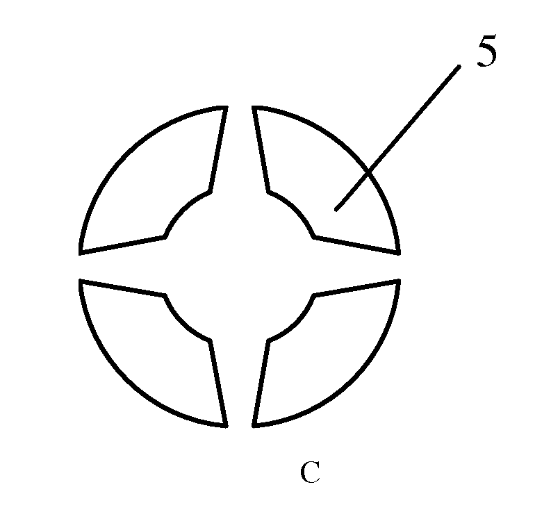
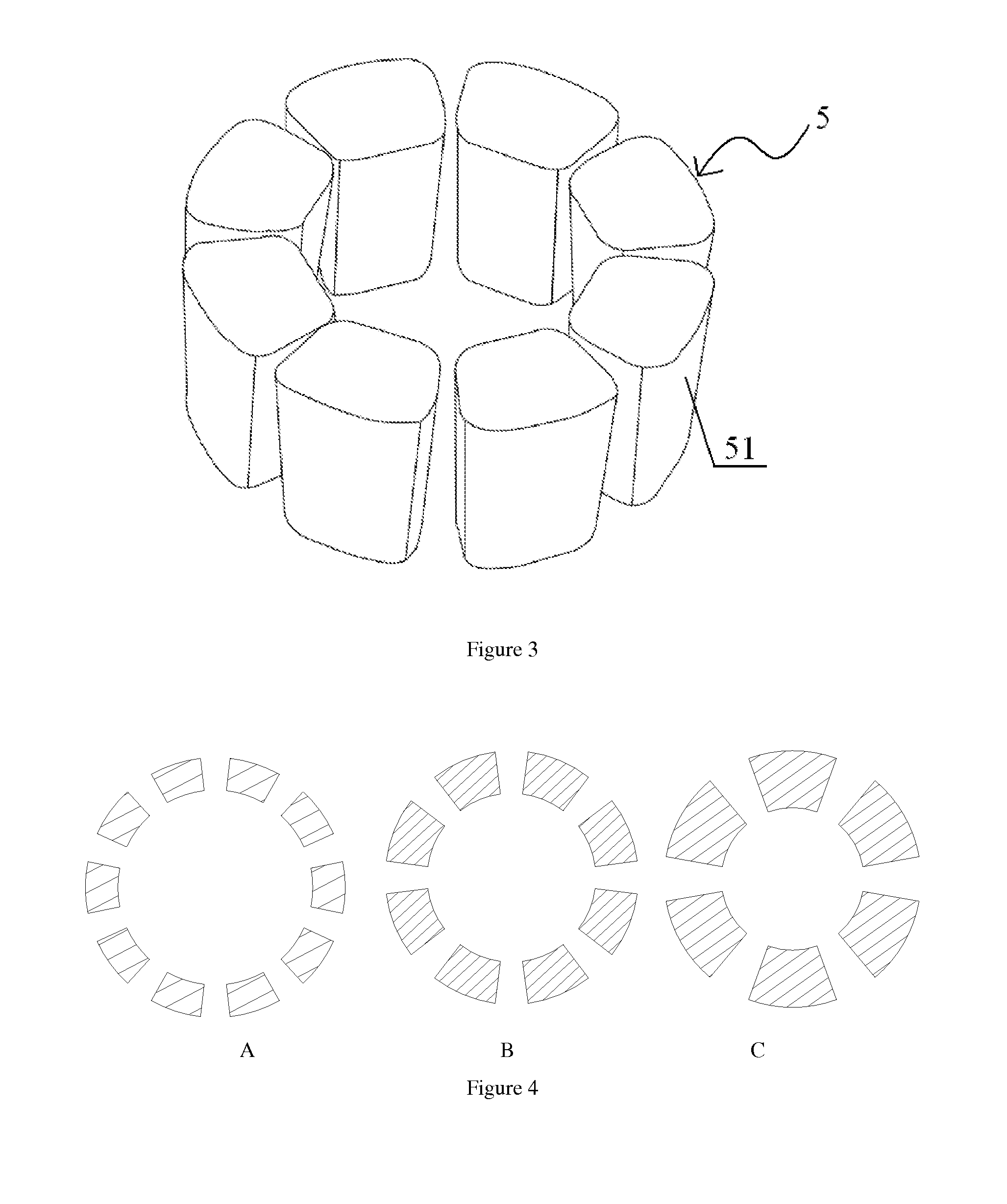
[0071]Example 2, comprises four layers: basal layer, microstructure layer, cover layer and oil-holding layer (as shown in FIG. 12A). The difference exists that there is only one microstructure in this device and this microstructure comprises four columns. The cross-section of each column is arc-shaped and a wider-inside-narrower-outside gap exists between each two adjacent columns to guide the growth of neural synapses (FIGS. 12B and 12C). The microstructure is 250 μm high, and has an inner diameter of 4 mm and outer diameter 4.2 mm. The gap structure has an inner arc length of 50 μm and outer arc length 30 μm.

[0072]Studying how different glial cells affect neurons with the microfluidic device included the following steps:

[0073]1) Device pretreatment: the same as in Example 3, the entire device is cleaned with ultrasonic washer and sterilized by U...


PUM


Abstract

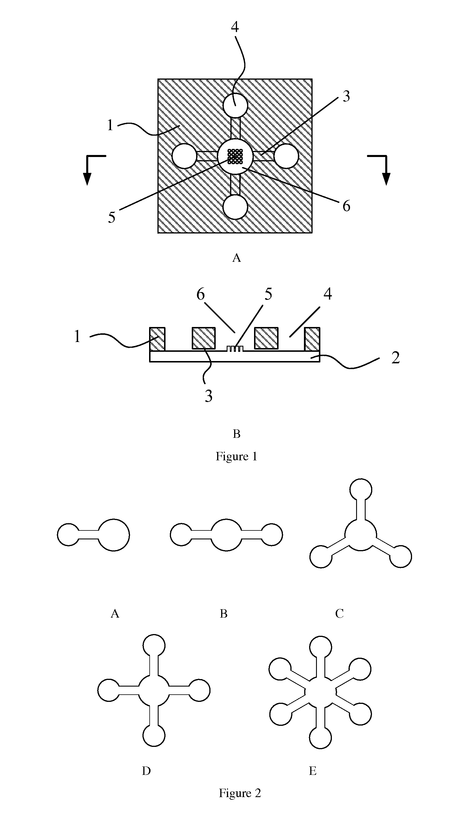
A micro fluidic device comprises one microstructure layer (5) and one cover layer (1), wherein the cover layer (1) is connected to the microstructure layer (5). The microstructure layer (5) comprises one bottom layer and a plurality of microstructures on it to position samples. The cover layer (1) comprises one top layer, one positioning well (6) and at least one inlet pool (4). The positioning well (6) is right above the microstructures and connected with each other. The inlet pools (4) and the positioning well (6) are connected by microchannels (3) which are formed between the microstructure layer (5) and the cover layer (1). The micro fluidic device can be applied in vitro fertilization, in determining how glial cells affect neurons, in constructing neural network and in detecting cell growth conditions.

Description

TECHNICAL FIELD[0001]The present invention relates to a microfluidic device and its uses for positioning of cells or organisms. This microfluidic device comprises functional microstructures for positioning of one or more cells / organisms, and, in some embodiments symmetrically aligned microchannels for cell motility screening.BACKGROUND ART[0002]Microfluidic technology refers to a reaction system which could handle a small amount of liquid or samples (10−9-10−18 L) in microchannels in the scale of tens to hundreds of microns (Whitesides, Nature (2006) 442:368-73). The first application of microfluidic technology in biochemical analysis is the research of capillary electrophoresis. Because of its rapid and high-throughput analysis capability on small sample volumes and its high sensitivity and integration, microfluidic technology has been introduced to research and analysis at the levels of molecules (e.g., nucleic acid, protein, etc.), cells, tissues and organisms.[0003]Cell position...

Claims


Application Information

Patent Timeline
IPC IPC(8): B01L3/00
CPCB01L3/5027C12M21/06C12M23/12C12M23/16
Inventor MA, RUIXIE, LANQIU, TIANWANG, LEIXING, WANLI
Owner CAPITALBIO CORP
Learn More