
Lithium ion secondary battery

Inactive Publication Date: 2013-12-26
HITACHI AUTOMOTIVE SYST LTD
View PDF2 Cites 5 Cited by
  • Summary
  • Abstract
  • Description
  • Claims
  • Application Information

AI Technical Summary

Benefits of technology

The present invention is about a lithium ion battery which can have a curved positive electrode without additional processes. This can be achieved by reducing the degree of curvature, which means the electrode is shaped like a fan with the unprocessed portion on the inside and the processed portion on the outside when viewed in a plan view. This results in a more efficient battery design without compromising its performance.

Problems solved by technology

For that reason, internal short-circuiting is generated due to dendrite deposition, or a battery performance is degraded.
However, in a process of thermally pressing the mix layers of the positive and negative electrodes, the metal foil strains, and the end portions of the positive and negative electrodes are not prevented from being misaligned due to this stain.

Method used


Image

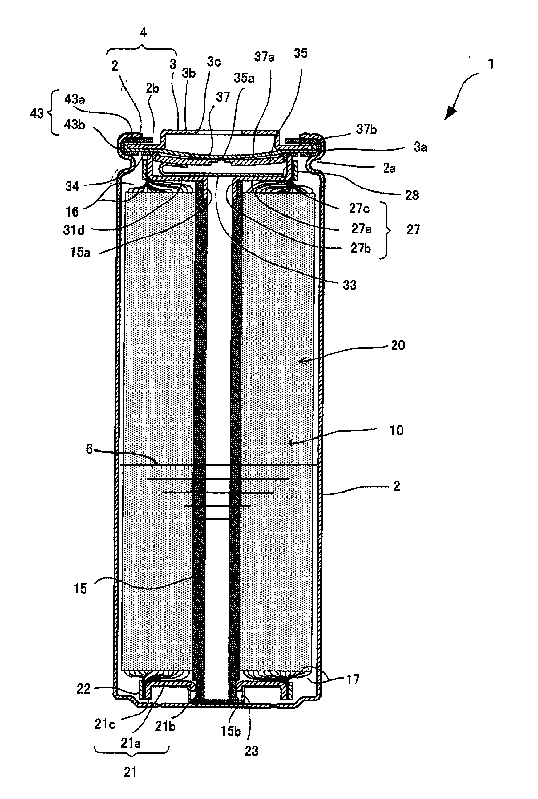
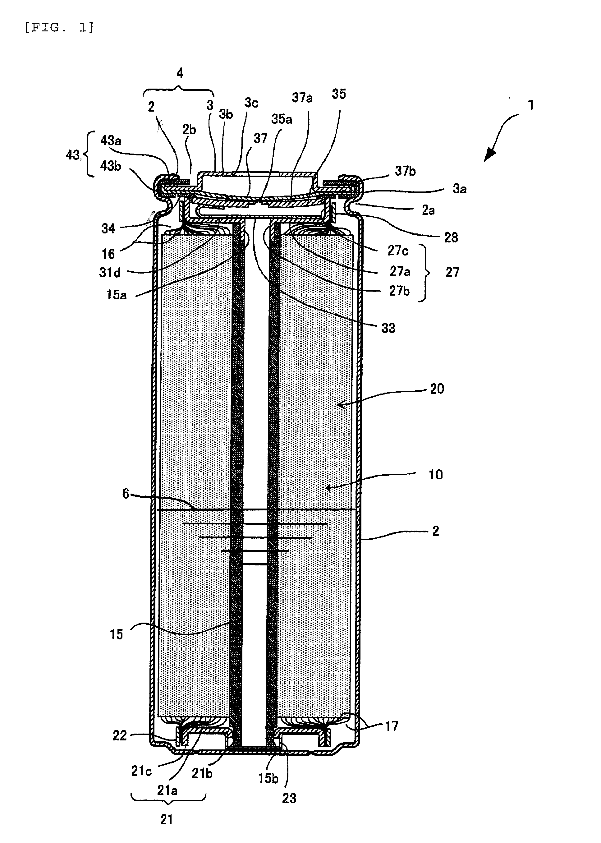
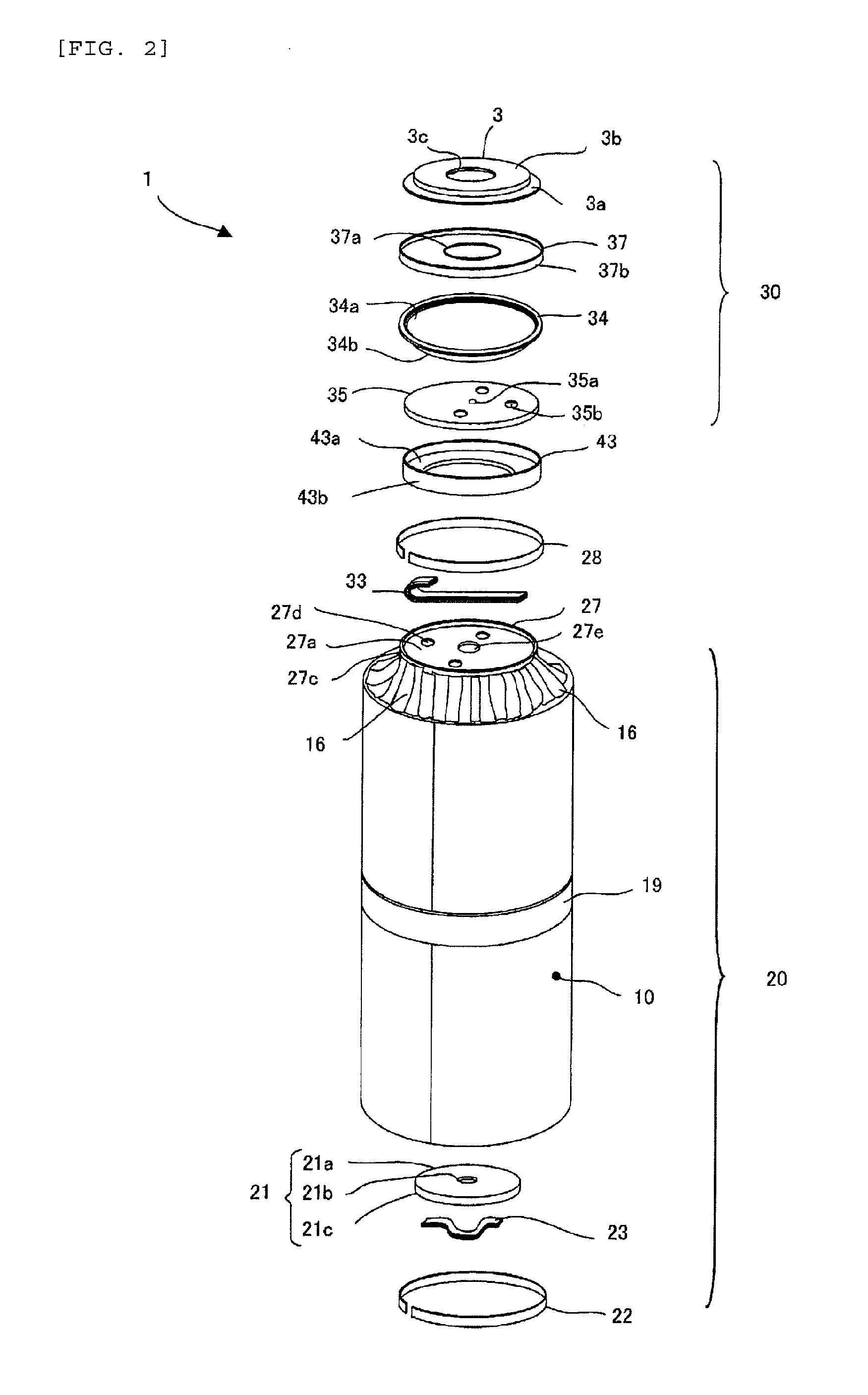
  • Lithium ion secondary battery
  • Lithium ion secondary battery
  • Lithium ion secondary battery

Examples


example 1

[0114]With the use of aluminum alloy containing Mn of 1% as the positive electrode metal foil 11a, the positive electrode 11 with (a / b)=0.025 which is a ratio of the width a of the continuous area portion 11c1 in the positive electrode mix unprocessed portion 11c, and the width b of the positive electrode mix layer 11b is fabricated. The 0.2% bearing force of the aluminum alloy is 246 MPa, and the strain at the 0.2% bearing force is 0.0067. Also, the inclination Y is 36.7 GPa.

[0115]The degree of fan d after the positive electrode mix layers 11b of the positive electrode 11 has been pressurized by the hot pressing roll is 1 mm. In this case, as described above, the degree of fan d is the amount of deformation when the length L of the positive electrode metal foil 11a is 1 m. In the following description, the degree of fan d is the amount of deformation when the length L of the positive electrode metal foil 11a is 1 m.

example 2

[0116]As with the example 1, with the use of aluminum alloy which are 246 MPa in 0.2% bearing force, 0.0067 in the strain at the 0.2% bearing force, and 36.7 GPa in the inclination Y, the positive electrode 11 with (a / b)=0.040 which is the ratio of the width a of the continuous area portion 11c1 in the positive electrode mix unprocessed portion 11c, and the width b of the positive electrode mix layer 11b is fabricated.

[0117]The degree of fan d after the positive electrode mix layers 11b of the positive electrode 11 has been pressurized by the hot pressing roll is 2 mm.

example 3

[0118]As with the example 1, with the use of aluminum alloy which are 246 MPa in 0.2% bearing force, 0.0067 in the strain at the 0.2% bearing force, and 36.7 GPa in the inclination Y, the positive electrode 11 with (a / b)=0.070 which is the ratio of the width a of the continuous area portion 11c1 in the positive electrode mix unprocessed portion 11c, and the width b of the positive electrode mix layer 11b is fabricated.

[0119]The degree of fan d after the positive electrode mix layers 11b of the positive electrode 11 has been pressurized by the hot pressing roll is 2 mm.


PUM


Abstract

A lithium ion secondary battery in which a winding type electrode group including a positive electrode having a positive electrode mix layer containing a lithium metal oxide, a negative electrode having a negative mix layer that stores and discharges lithium ions, and separators arranged on inner and outer peripheries of the positive electrode and the negative electrode is housed, and a nonaqueous electrolyte is poured, within a battery container, the positive electrode has one side edge along a longitudinal direction thereof exposed as a positive electrode mix unprocessed portion, and a positive electrode mix layer coated in the other area on both surfaces of a metal foil made of an aluminum alloy.

Description

TECHNICAL FIELD[0001]The present invention relates to a lithium ion secondary battery, and more particularly to a lithium ion secondary battery which is capable of improving a performance of a positive electrode on which a positive electrode mix containing a positive electrode active material is formed.BACKGROUND ART[0002]One type of the lithium ion secondary batteries includes a winding type electrode group that winds a positive electrode having a positive electrode mix layer, a negative electrode having a negative electrode mix layer, and a separator that interposed between those electrodes.[0003]The positive electrode mix layer contains a positive electrode active material made of lithium metal oxide, and the negative electrode mix layer contains a negative electrode active material that can store and discharge lithium ions such as graphite. The separator has holes through which the lithium ions penetrate. Lithium is stored in a state of ions between the positive electrode mix la...

Claims


Application Information

Patent Timeline
IPC IPC(8): H01M10/04H01M4/13H01M50/538
CPCH01M10/0431H01M4/13H01M4/661H01M10/0587H01M4/139Y02E60/10H01M50/538Y02P70/50
Inventor NANAUMI, TAKESHIMITANI, TAKAYUKISUZUKI, KATSUNORISHINOHARA, HIDEKI
Owner HITACHI AUTOMOTIVE SYST LTD
Learn More