
Method for in situ coating a tower solar receiver

a technology of solar receiver and in situ coating, which is applied in the direction of solar heat collector safety, light and heating apparatus, coatings, etc., can solve the problems of difficult curing of the curing process, the product has presented durability problems, and the documentation that can be found about the experience of coating application methodology, in combination with the use of solar technology, is still scarce, and the effect of reducing the cost of curing

Inactive Publication Date: 2013-12-26
ABENGOA SOLAR NEW TECH SA
View PDF3 Cites 2 Cited by
  • Summary
  • Abstract
  • Description
  • Claims
  • Application Information

AI Technical Summary

Benefits of technology

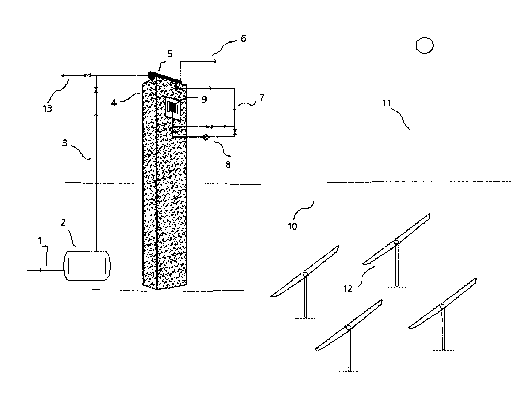
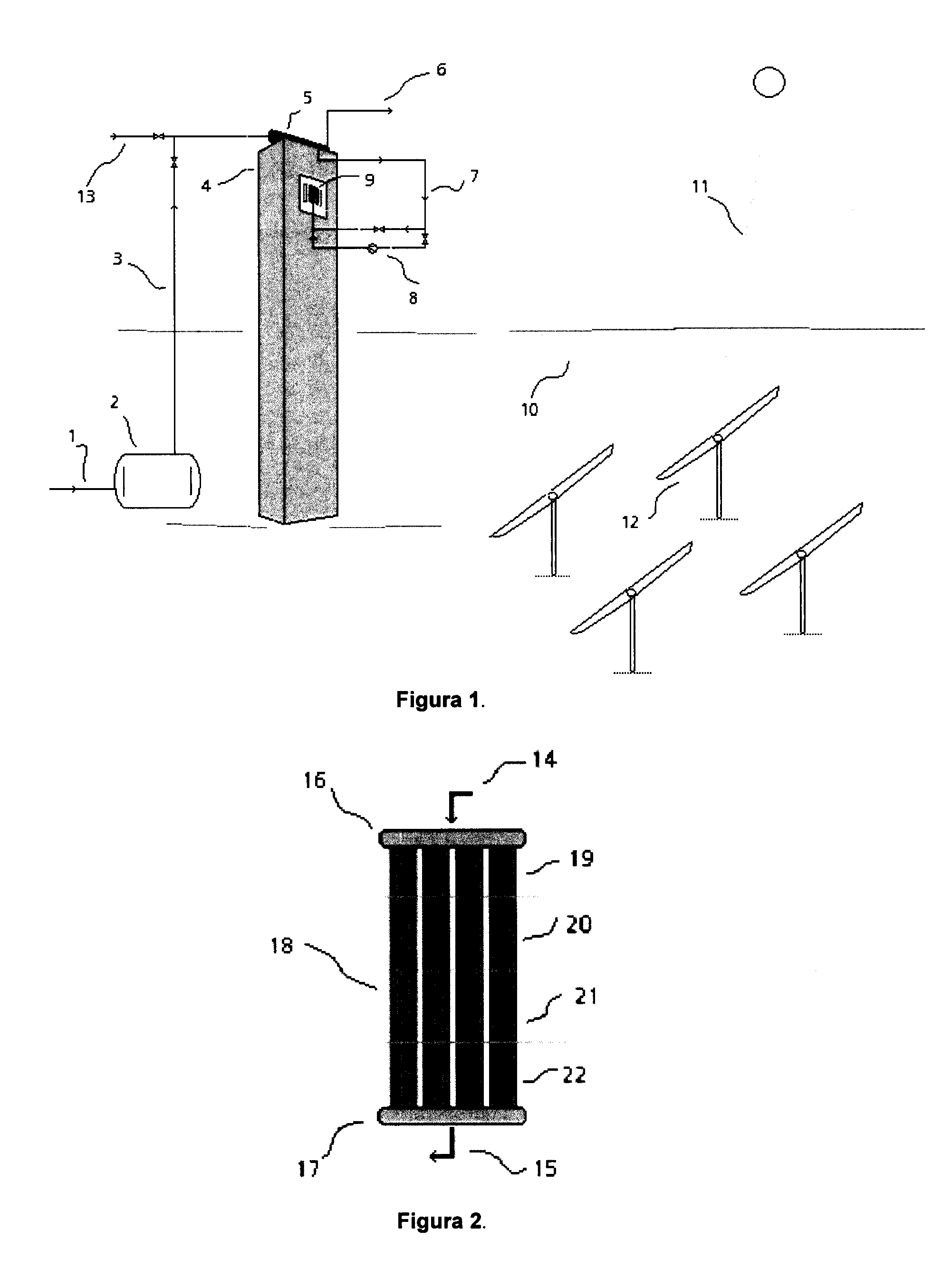
This patent proposes a method for coating tower solar receivers to increase their durability and efficiency. The method addresses common problems like cracking and flaking of the coating, which can reduce the heat absorption of the receiver and cause oxidation. The proposed method involves a two-step process where the coating is applied and then cured using a circulating steam system. This curing method prevents the oxidation of the receiver between steps and ensures the evaporation of volatile components prior to curing, resulting in a more complete and complete coating.

Problems solved by technology

There is an extensive commercial offer within the market of coatings to be potentially used in tower solar receivers; however, very few have been developed specifically for said application, and therefore, tested on said solar components.
Therefore, the documentation that can be found about experiences in coating application methodology, in combination with the use of solar technologies, is still scarce.
The coating with the most experience in tower solar receivers is Pyromark® 2500; however, said product has presented durability issues when exposed to the operating conditions of the receiver.
In the case of solar receivers, their size and the complexity of their installation makes the renewal of the absorbing coating and the curing thereof difficult, due to the need to dismount and displace the receiver from the top of the tower to ovens which sizes may be adjusted to the size of the receiver.

Method used


Image

  • Method for in situ coating a tower solar receiver
  • Method for in situ coating a tower solar receiver

Examples


Embodiment Construction

[0013]Tower solar receivers receive concentrated solar radiation by means of a heliostat field. These receivers, through which a heated working fluid circulates, require the application of an absorbing coating on their surfaces. This coating, in addition to increasing the absorptivity of the surface, also protects the receiver against environmental factors and corrosion.

[0014]The absorbing coatings currently used in the receivers are silicon-based coatings, which provide them with good resistance to high temperatures, having black pigments that grant the absorbing property.

[0015]Due to the fact that the protection of a surface with a coating depends on the surface preparation and on the success of the deposition process (thickness of the deposited film, continuity thereof, application method), in addition to the characteristics of the product itself, the methodology to be used in all the steps of the application process needs to be specified.

[0016]The solution to the low durability ...


PUM

PropertyMeasurementUnit
Temperatureaaaaaaaaaa
Timeaaaaaaaaaa
Temperatureaaaaaaaaaa

Abstract

The invention relates to a method for in situ coating a tower solar receiver in order to protect the surface of the receiver from corrosion and to increase absorptivity of same, which is carried out in several steps: surface preparation, application of the coating, curing, optional vitrification, and controlled cooling. The surface preparation is done by zones depending on the size of the receiver, a methodology that enables an intercalated application of the coating in order to minimize the risk of corrosion. The curing stage is carried out by supplying steam to the inside of the receiver tubes, and temperature requirements above the operating limits of the boiler are adjusted with the solar field as support system. Vitrification is done using saturated steam traveling through the receiver tubes and concentrating solar radiation on the surface of the receiver from the solar field.

Description

TECHNICAL SECTOR OF THE INVENTION[0001]This invention belongs to the technical sector that encompasses the procedures to apply liquids or other fluid materials to surfaces, with the prior treatment thereof.[0002]More specifically, it relates to an application method of absorbing coatings to tower solar receivers. The method includes the surface preparation, application of the coating, curing, and in situ vitrification of the receiver.BACKGROUND OF THE INVENTION[0003]In tower solar receiver systems, a field of heliostats or mobile mirrors that are oriented according to the position of the sun, reflect solar radiation in order to concentrate the same on a receiver that is located at the top of a tower. The receiver is in charge of transferring the heat that is received to a working fluid such as water, molten salts, etc., with the purpose of generating steam that will expand in a turbine coupled to a generator for the production of electricity. These receivers have a special coating t...

Claims


Application Information

Patent Timeline
IPC IPC(8): F24J2/48F24J2/07F24S20/20
CPCF24J2/485F24J2/07C23D5/00F24S40/40F24S20/20F24S70/20Y02E10/40B05D3/0254
Inventor CLAVIJO RIVERA, ERIKA PATRICIAMARTINEZ SANZ, NOELIABARRAGAN JIMENEZ, JOSE
Owner ABENGOA SOLAR NEW TECH SA
Learn More