
Torque tube supporter and solar tracker using the same

Inactive Publication Date: 2011-10-20
UST SOLAR INC
View PDF1 Cites 59 Cited by
  • Summary
  • Abstract
  • Description
  • Claims
  • Application Information

AI Technical Summary

Benefits of technology

[0009]Accordingly, the present invention has been made keeping in mind the above problems occurring in the related art, and the present invention intends to propose a torque tube supporter capable of improving long-term durability and precisely tracking sunlight, and minimizing overload applied onto structures, and a solar tracker using the same.
[0016]The cylindrical torque tube is retained by the bearing such that distortion stress occurring on the torque tube is uniformly distributed, thereby preventing degradation of long-term durability.
[0018]Further, since the coupling structure of the bearing, the bearing cover, and the half journal for supporting the cylindrical torque tube is simple, the torque tube supporter can be quickly mounted with ease at the scene.
[0019]Further, since the bearing is covered on the whole circumference with the first and second bearing covers in a close-contact manner, even upon revolution, the stress distribution over the bearing becomes constant, thereby reducing the risk of breakage.
[0020]Further, since the upper portion of the half journal is of an arcuate shape, the half journal does not interfere with the revolution of the bearing, thereby increasing the efficiency of using the parts.
[0021]Further, since the rear portion of the bearing cover has a bent portion extending opposite the radial direction, the bearing is prevented from deviating from the bearing cover, keeping the concentricity of the torque tube constant.

Problems solved by technology

However, since the torque tube of the related art has a rectangular section, the torque tube has the problem of when used for a long time running the risk of suffering from distortion and deformation caused by distortion stress generated upon its making revolutions.
Another problem occurs wherein when an angle of the torque tube is controlled by an action of a driver, precise control of the angle is difficult to implement because of the rectangular section of the torque tube.
A further problem occurs wherein the sectional shapes of the torque tube and a bearing supporting the torque tube are different from each other, so that stress in the section of the bearing is unevenly distributed and thus overran excessive load is applied onto the bearing.

Method used


Image

  • Torque tube supporter and solar tracker using the same
  • Torque tube supporter and solar tracker using the same
  • Torque tube supporter and solar tracker using the same

Examples


Embodiment Construction

[0031]Reference will now be made in greater detail to a preferred embodiment of the invention, an example of which is illustrated in the accompanying drawings. Wherever possible, the same reference numerals will be used throughout the drawings and the description to refer to the same or like parts.

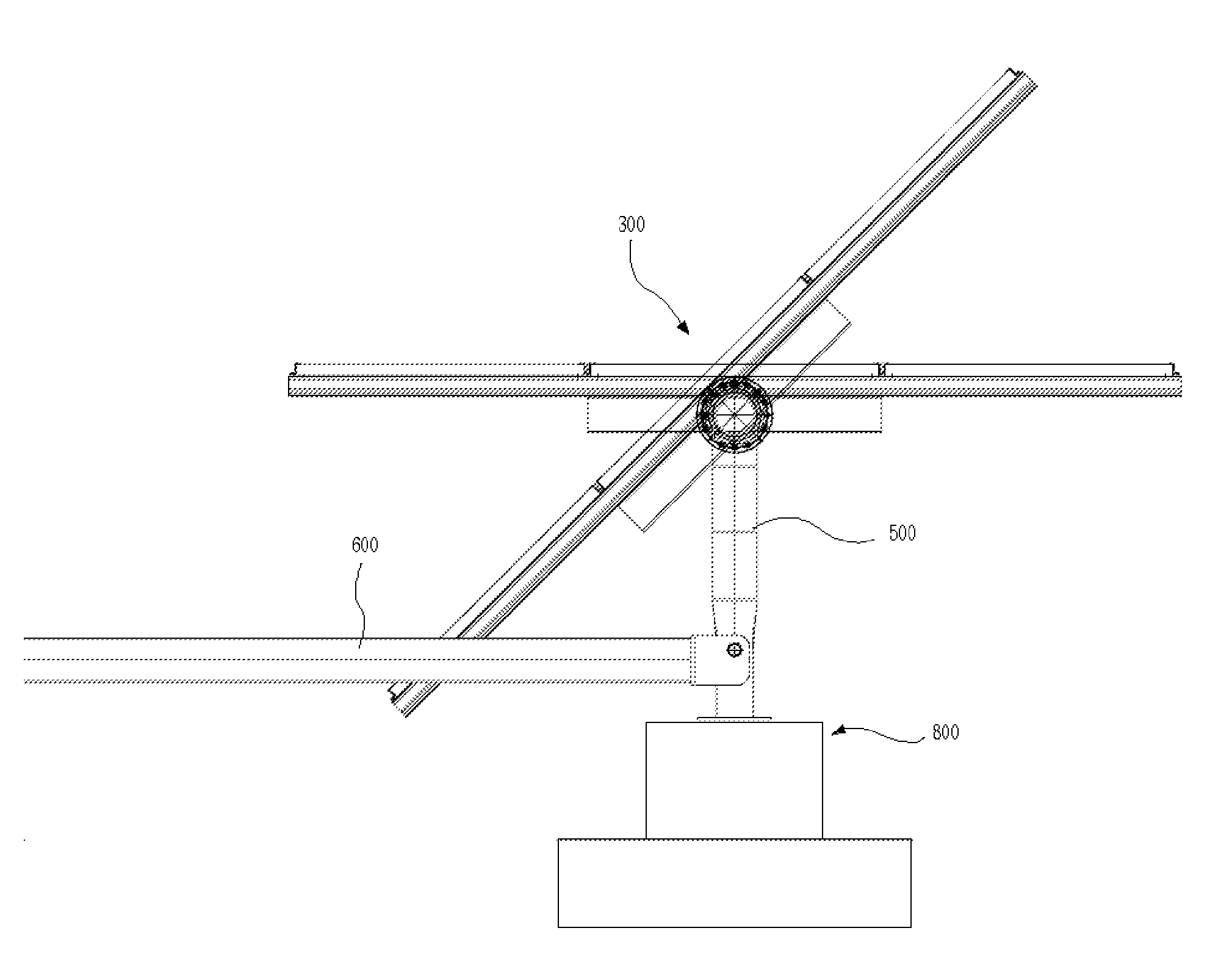
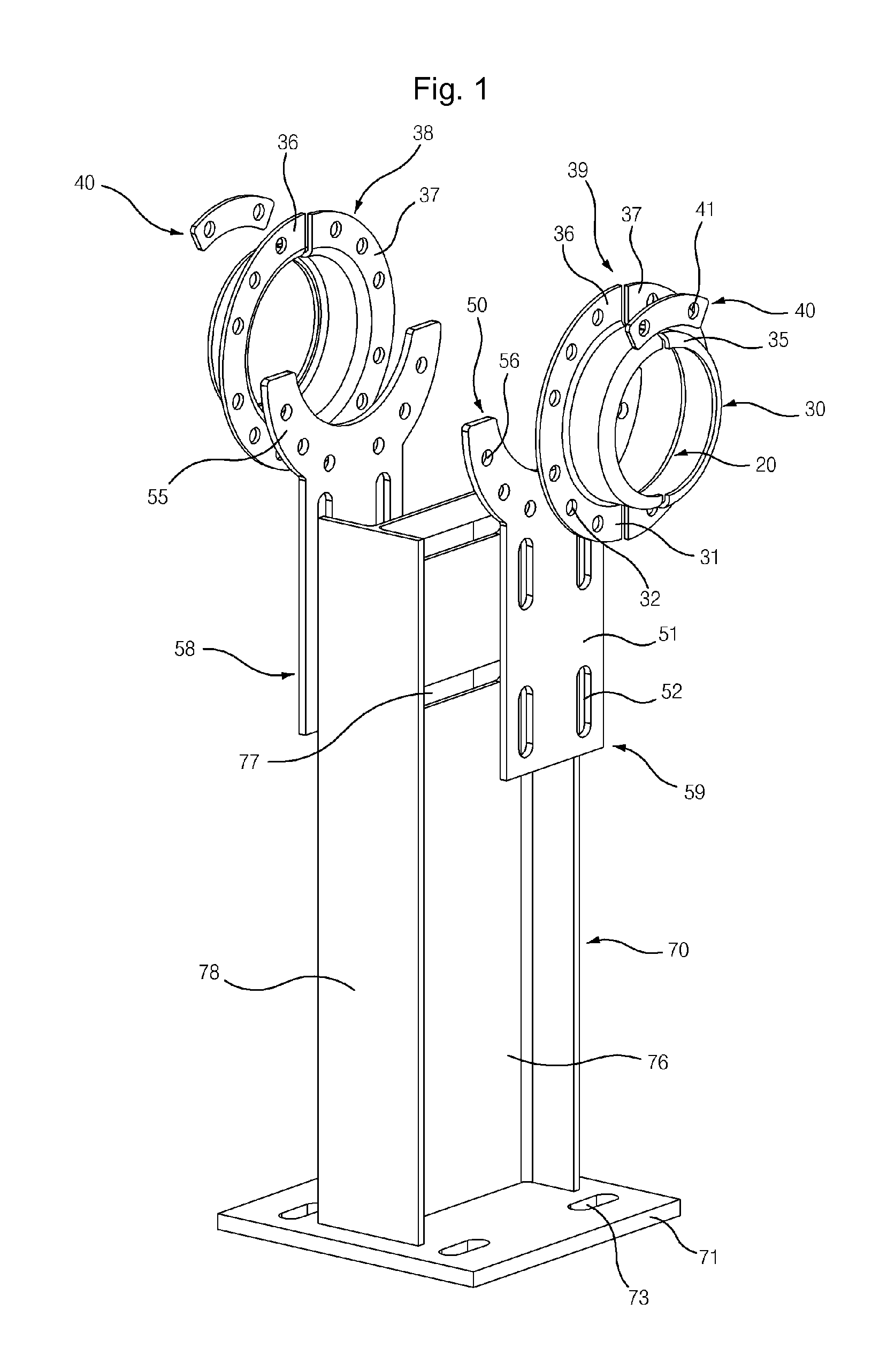
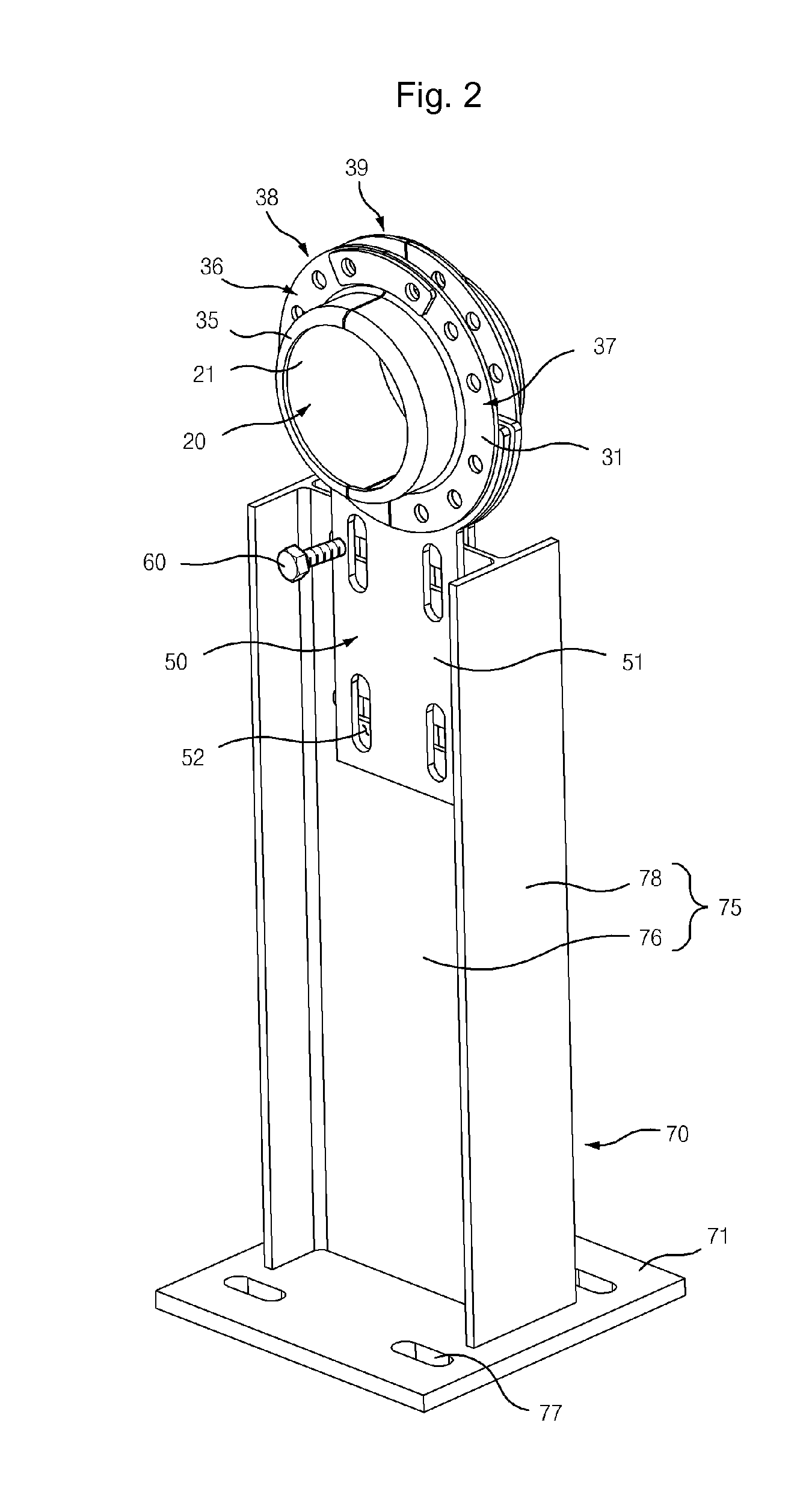
[0032]FIG. 1 is an exploded perspective view showing a torque tube supporter according to an embodiment of the invention, FIG. 2 is a perspective view showing the assembled state of the torque tube supporter, FIG. 3 is a front view of FIG. 2, FIG. 4 is a side view of FIG. 2, FIG. 5 is a front view showing a solar tracker according to an embodiment of the invention, FIG. 6 is a side view showing the assembly of a lever arm and a link member according to an embodiment, and FIG. 7 is a view showing the installed state of the solar tracker according to an embodiment.

[0033]The torque tube supporter according to an embodiment will now be described with reference to FIGS. 1 to 4.

[0034]The torque ...


PUM


Abstract

A torque tube supporter and a solar tracker using the same are provided. The torque tube supporter includes a cylindrical bearing supporting a cylindrical torque tube, a bearing cover having a cylindrical middle portion for supporting the bearing, a flange radially protruding from the circumference of the bearing cover, a half journal section having an arcuate upper portion to which the flange is fixed, and a post supporting the half journal section.

Description

BACKGROUND OF THE INVENTION[0001]1. Field of the Invention[0002]The present invention relates, in general, to a torque tube supporter and a solar tracker using the same, and more particularly to a supporter for supporting a cylindrical torque tube and a solar tracker using the same.[0003]2. Description of the Related Art[0004]Generally, solar trackers are devices that allow a solar panel to track sunlight in relation to the position of the sun such that the horizontal surface of the solar panel is placed perpendicular to the sun in order to improve the efficiency with which electricity is generated.[0005]Recent interest in solar energy has increased and a variety of solar trackers are being proposed. Korean Patent No. 0864215 discloses a solar tracker in which a solar panel is mounted not in a single module frame, but in a module frame using a plurality of crank axes. Korean Patent Laid-open Publication No. 2009-0108261 discloses a solar tracker that ensures that the relative revolv...

Claims


Application Information

Patent Timeline
IPC IPC(8): H01L31/052F16C35/02F24S50/20
CPCF24J2/541F24J2002/5451F24J2002/5468H02S20/00Y02E10/47Y02E10/50F24J2002/5482F24S30/425F24S2030/131F24S2030/136F24S2030/15H02S20/32
Inventor KIM, SCOTT W.
Owner UST SOLAR INC
Learn More