
Internal combustion engine and hand-held power tool with internal combustion engine

a technology of internal combustion engine and power tool, which is applied in the direction of machines/engines, mechanical equipment, cylinders, etc., can solve the problems of crankcase wall remains, engine operation is worsened, and the exhaust behavior and exhaust value are worsened

Inactive Publication Date: 2013-12-26
ANDREAS STIHL AG & CO KG
View PDF4 Cites 0 Cited by
  • Summary
  • Abstract
  • Description
  • Claims
  • Application Information

AI Technical Summary

Benefits of technology

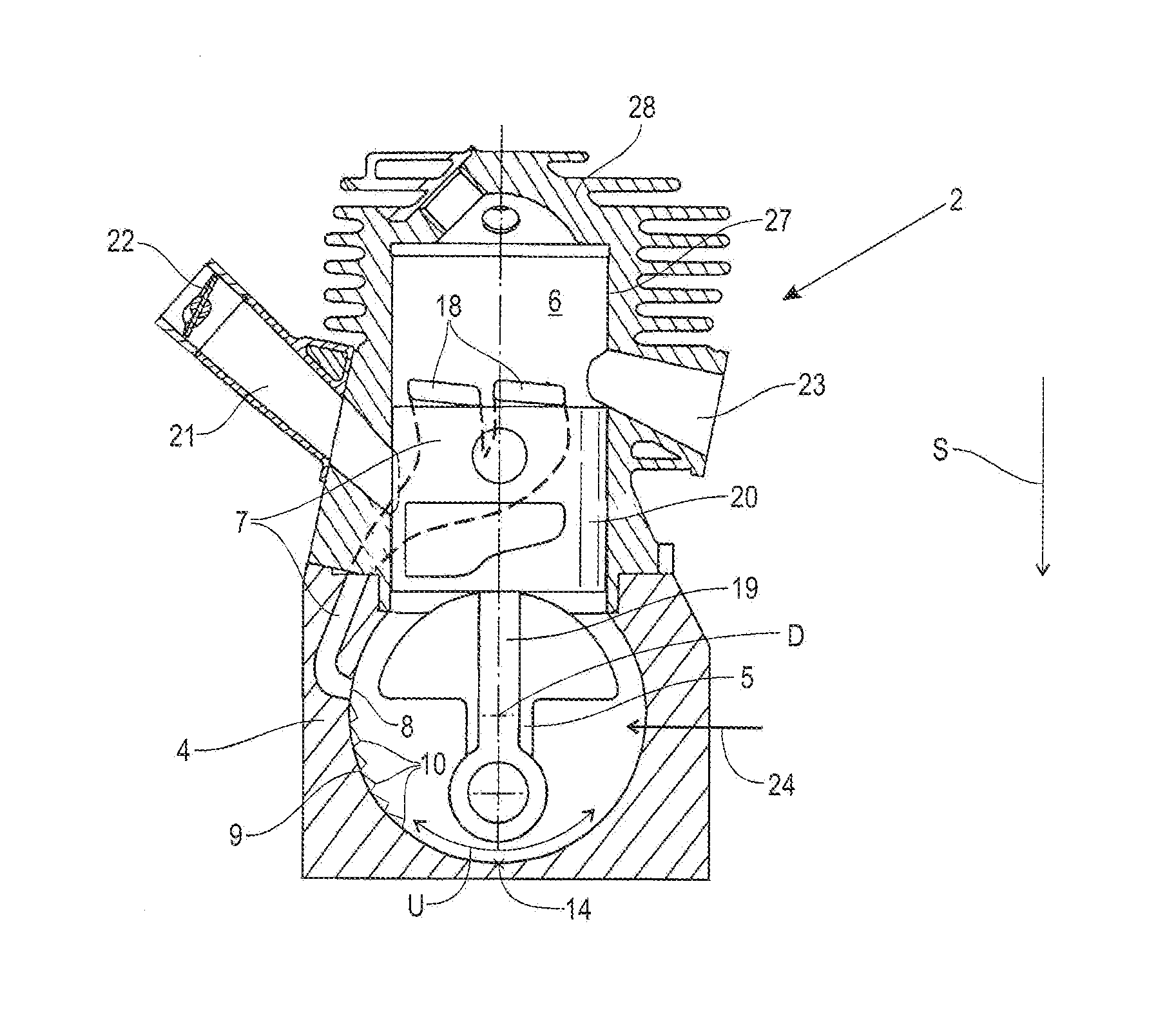
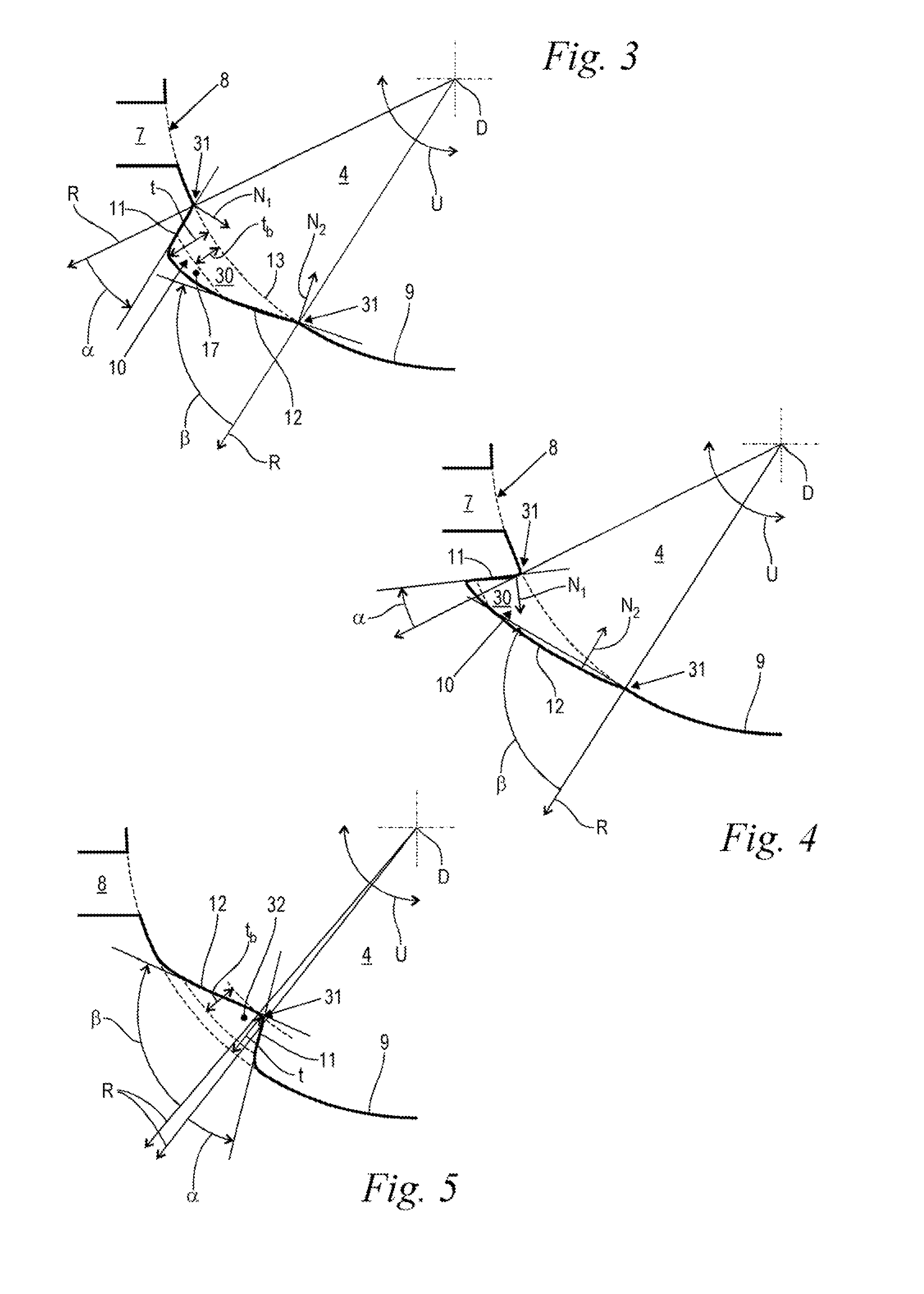
The present invention relates to an improved internal combustion engine that prevents fuel from entering the transfer passage when the power tool is positioned in a certain way. The engine has angled surfaces that obstruct the fuel's flow and allow it to drain out in the opposite direction. The angled surfaces are positioned in opposite directions when measured from the radial direction, which maximizes engine efficiency. The fuel retaining device extends across the entire width of the crankcase and is formed by a depression in the inner contour of the crankcase. This reduces the volume of the crankcase and improves fuel guide, mixture formation, and prevents fuel deposition.

Problems solved by technology

This produces an excessively rich fuel / air mixture and causes worsening of the exhaust behavior and exhaust values and can also lead to worsening of engine operation up to the point of stalling of the engine.
It is a disadvantage in this connection that between the fuel retaining devices and the inlet port of the transfer passage the contour of the crankcase wall remains undisturbed and fuel can collect thereat and flow into the transfer passage.
As soon as a certain excessive quantity of fuel has accumulated, the retaining action of the fuel retaining devices is no longer sufficient so that the fuel drains in an undesirable way and may pass into the transfer passage.

Method used


Image

  • Internal combustion engine and hand-held power tool with internal combustion engine
  • Internal combustion engine and hand-held power tool with internal combustion engine
  • Internal combustion engine and hand-held power tool with internal combustion engine

Examples


Embodiment Construction

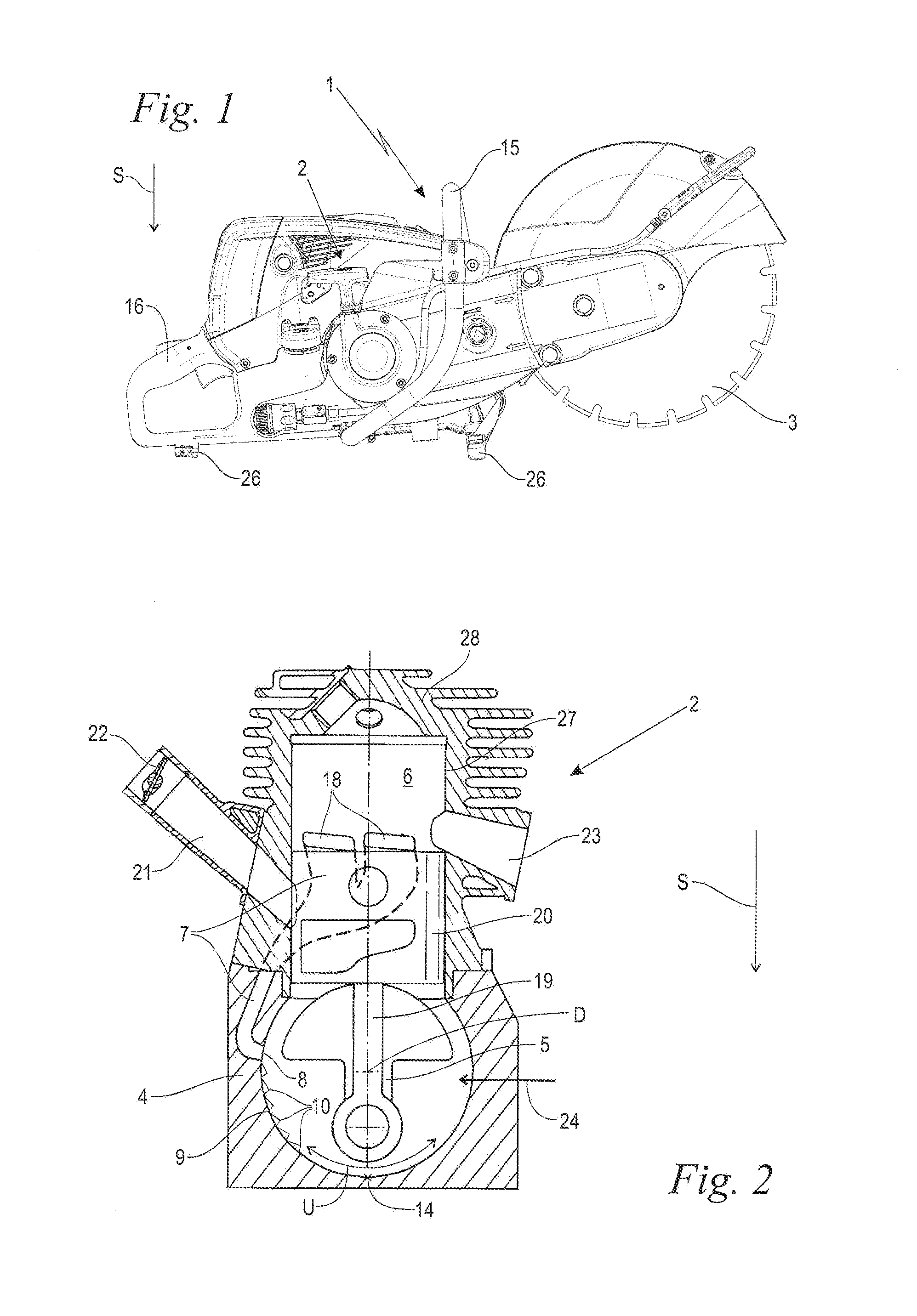
[0028]FIG. 1 is a side view of the power tool 1 according to the invention exemplified by a cut-off machine. However, a motor chainsaw, a trimmer, a hedge trimmer or the like can be used also. The power tool 1 comprises a tool member 3 which is in this case a cutter wheel and which in operation is driven by an internal combustion engine 2 arranged in the power tool 1 and illustrated in FIG. 2.

[0029]The power tool 1 comprises a front handle 15 arranged at the leading end facing the tool member 3 and a read handle 16 that is arranged at the end facing away from the tool member 3, wherein the operator lifts and guides the power tool 1 by gripping with one hand the front handle 15 and with the other hand the rear handle 16. Also, the power tool 1 is provided with legs 26 by means of which the power tool can be placed onto the ground or floor.

[0030]The power tool 1 is illustrated in its usual working position relative to the direction of gravity S. This usual working position results fro...


PUM


Abstract

An internal combustion engine of a hand-held power tool has a crankcase having a circumferential wall extending in a circumferential direction of the crankcase. A crankshaft is supported so as to be rotatable about an axis of rotation within the crankcase. At least one transfer passage extends from the crankcase into the cylinder of the engine, wherein the transfer passage has an inlet port at the crankcase. At least one fuel retaining device is disposed on the circumferential wall of the crankcase. A radial direction, starting at the axis of rotation of the crankshaft and extending outwardly, extends through the at least one fuel retaining device. The at least one fuel retaining device has a depth in the radial direction and a length in the circumferential direction. The at least one fuel retaining device, relative to the radial direction, has an asymmetric cross-section in the circumferential direction.

Description

BACKGROUND OF THE INVENTION[0001]The invention relates to an internal combustion engine of a hand-held power tool for driving the tool member of the power tool wherein the internal combustion engine comprises a crankcase, a crankshaft that is rotatably supported in the crankcase so as to rotate about an axis of rotation, a cylinder, and at least one transfer passage that extends from the crankcase into the cylinder. The transfer passage opens by means of an inlet port into the crankcase. The crankcase has a circumferential wall extending in the circumferential direction and the circumferential wall is provided with at least one fuel retaining device. A radial direction extends from the axis of rotation of the crankshaft through the fuel retaining device and the fuel retaining device has a depth in the radial direction and a length in the circumferential direction. The invention further relates to a power tool provided with such an internal combustion engine.[0002]Hand-held motor-dri...

Claims


Application Information

Patent Timeline
Patent Type & Authority Applications(United States)
IPC IPC(8): F02B63/02
CPCF02B63/02F02B2075/025
Inventor KLATT, CLEMENSPAA, ANDREAS
Owner ANDREAS STIHL AG & CO KG
Learn More