Method for measuring thickness of print products passing spaced apart at specific distances in a conveying flow through a measuring device

a technology of measuring device and print product, which is applied in the direction of piling separation, using electrical/magnetic means, instruments, etc., can solve the problems that the method cannot be used with extremely thin products, and individual equalization of the measuring device is required, so as to prevent undesirable markings on the print produ

Inactive Publication Date: 2009-02-03
MULLER MARTINI HLDG
View PDF11 Cites 0 Cited by
  • Summary
  • Abstract
  • Description
  • Claims
  • Application Information

AI Technical Summary

Benefits of technology

[0012]It is an object of the present invention to provide a measuring device that is capable of measuring the thickness of print products in a conveying flow, wherein the thicknesses cover a wide range, and wherein the measuring device substantially prevents undesirable markings on the print products. It is a further object of the present invention to provide such a measuring device that is no more expensive than existing thickness measuring devices.

Problems solved by technology

These methods, however, can only be used with extremely thin products.
Solutions of this type have the disadvantage that in most cases individual equalization of the device is required.
Another disadvantage is that the analog signal which represents the capacitance is subject to interference, so that involved configurations are often necessary.

Method used


Image

  • Method for measuring thickness of print products passing spaced apart at specific distances in a conveying flow through a measuring device
  • Method for measuring thickness of print products passing spaced apart at specific distances in a conveying flow through a measuring device
  • Method for measuring thickness of print products passing spaced apart at specific distances in a conveying flow through a measuring device

Examples


Embodiment Construction

[0021]Embodiments of the invention are discussed in detail below. In describing embodiments, specific terminology is employed for the sake of clarity. However, the invention is not intended to be limited to the specific terminology so selected. While specific exemplary embodiments are discussed, it should be understood that this is done for illustration purposes only. A person skilled in the relevant art will recognize that other components and configurations can be used without parting from the spirit and scope of the invention. All references cited herein are incorporated by reference as if each had been individually incorporated.

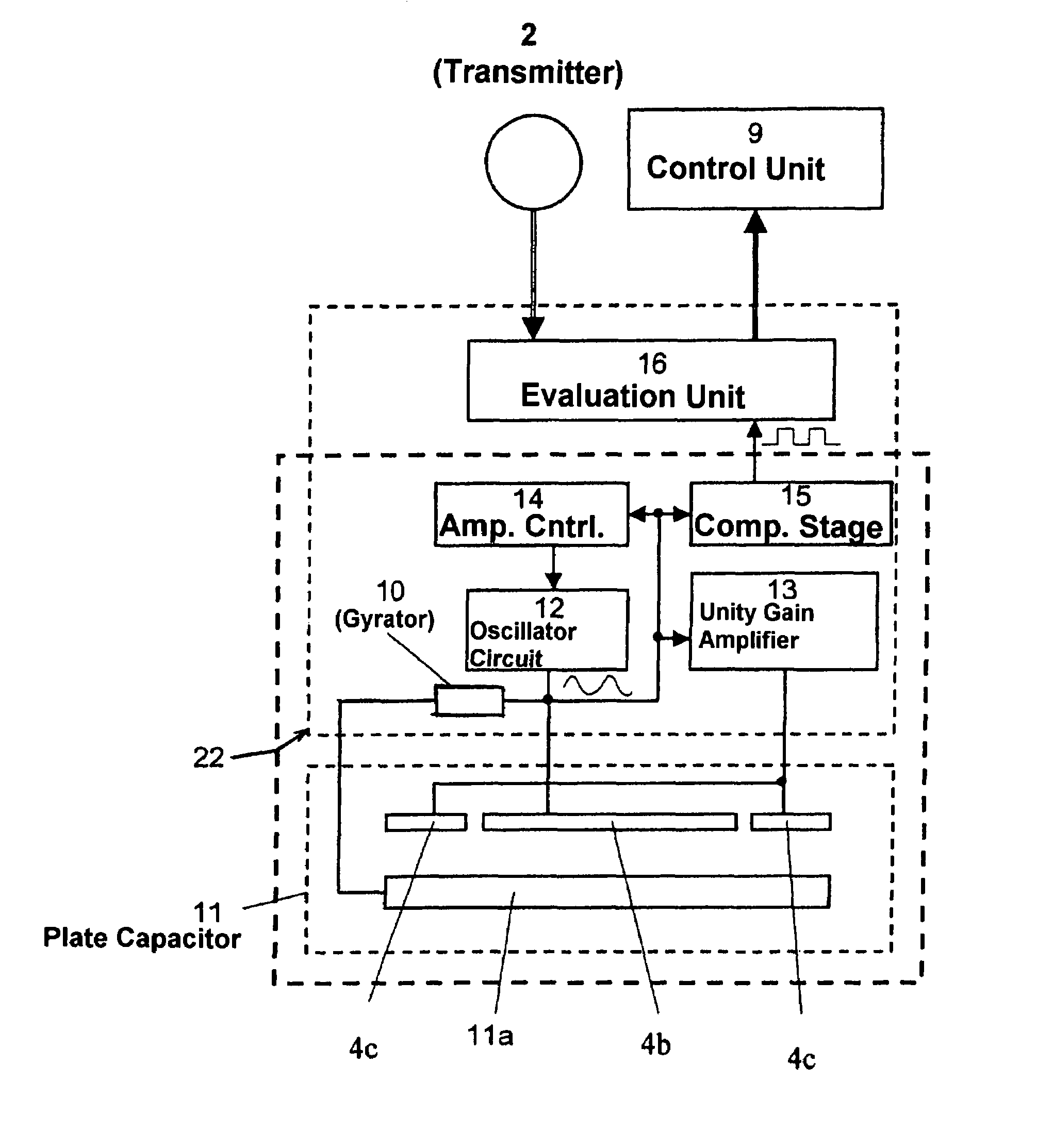
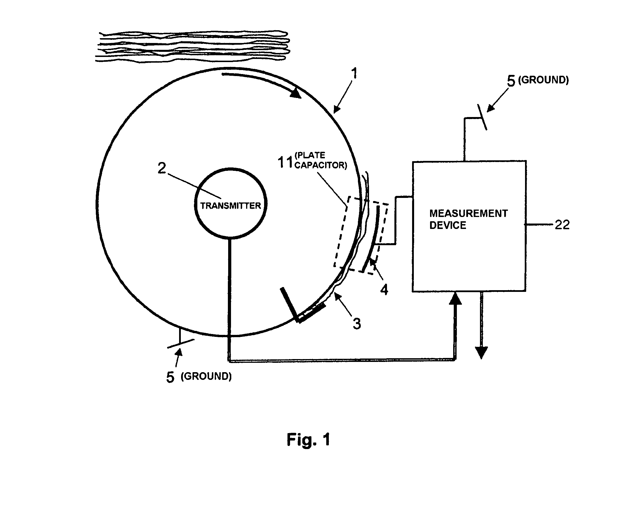
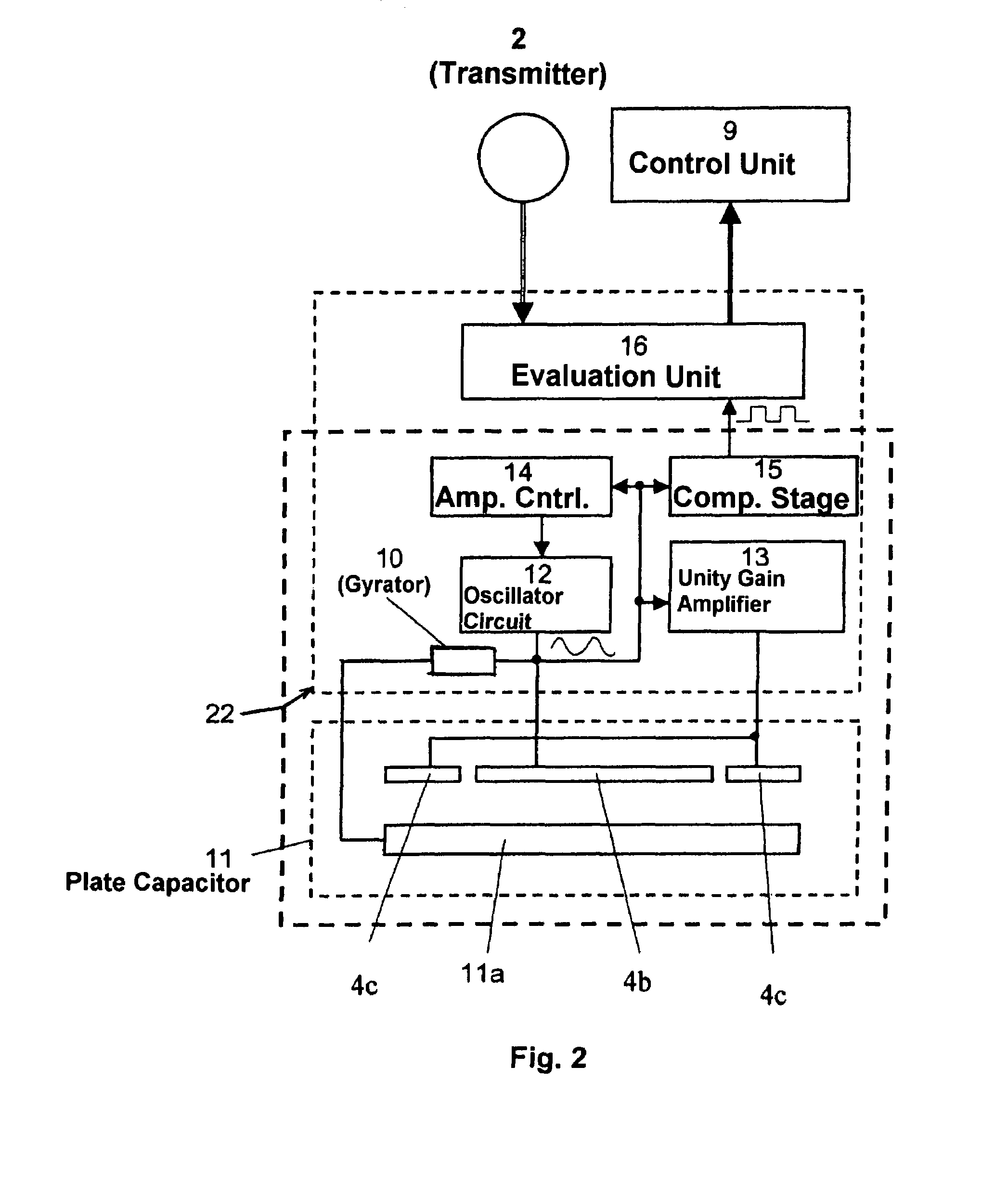
[0022]Referring to FIG. 1, an exemplary apparatus for carrying out the method of the present invention is shown. As shown in FIG. 1, the apparatus can take the form of a feeder comprising a conveying drum 1 for separating print products 3, although other configurations are possible. The method and apparatus make use of the effect that a plate capacitor 11...


PUM


Abstract

A device for measuring the thickness of print products in a conveying flow includes a plate capacitor having a first plate and a second plate located on opposite sides of the print products. The plate capacitor is adapted to measure capacitance of the print products passing between the first plate and the second plate. A LC oscillator circuit is attached to the plate capacitor.

Description

CROSS-REFERENCE TO RELATED APPLICATIONS[0001]This application claims the priority of European Patent Application No. 04405601.8, filed on Sep. 20, 2004, the entire content of which is incorporated herein by reference.BACKGROUND OF THE INVENTION[0002]1. Technical Field of the Invention[0003]The invention relates generally to a method for measuring the thickness of print products, and more particularly, to a method for measuring the thickness of print products flowing through a measuring device in spaced intervals.[0004]2. Related Art[0005]Conveying systems that operate on a timed cycle commonly include a rotating drum having grippers that grip print products to be separated, and transfer the print products to one or more conveying belts. The thickness of the print products can be measured on the rotating drum or on the downstream conveying device (e.g. between belts). Known systems detect the product thickness, for example, by mechanical means, for example, by scanning the thickness ...

Claims


Application Information

Patent Timeline
Patent Type & Authority Patents(United States)
IPC IPC(8): G01R27/26G01B7/02B65H7/12
CPCB65H7/125B65H2553/23
Inventor DUSS, HANSPETER
Owner MULLER MARTINI HLDG
Why Eureka
Try Eureka