Eureka AIR delivers breakthrough ideas for toughest innovation challenges, trusted by R&D personnel around the world.

Full-Bridge Magnetoresistive Rotation Sensors and Mass Fabrication Method

a technology of magnetoresistive rotation sensors and full-bridge magnetoresistive, applied in the direction of instruments, galvano-magnetic devices, magnetic field measurement using galvano-magnetic devices, etc., can solve the problems of insufficient development of high-sensitivity devices with sufficient yield for low-cost mass production, insufficient sensitivity and/or dynamic range, cost, reliability and other factors, etc., to achieve the largest possible output signal, reduce the effect of process-dependent variation in the sensor transfer curv

Active Publication Date: 2013-12-19
MULTIDIMENSION TECH CO LTD
View PDF3 Cites 26 Cited by
  • Summary
  • Abstract
  • Description
  • Claims
  • Application Information

AI Technical Summary

Benefits of technology

The present invention provides a cost-effective method for producing high-spec and high-output angle sensors using standard semiconductor packaging processes. The design utilizes a standard multi-chip semiconductor packaging process to create push-pull full-bridge magnetic angle sensors, which provide the greatest output signal and are resistant to temperature changes and process variations. This method offers a reliable and affordable solution for producing high-accuracy angle sensors.

Problems solved by technology

However, they all suffer from various limitations well known in the art, for example, excessive size, inadequate sensitivity and / or dynamic range, cost, reliability and other factors.
Although MTJ devices are compatible with standard semiconductor fabrication processes, methods for building high sensitivity devices with sufficient yield for low cost mass production have not been adequately developed.
In particular, yield issues due to difficulty in MTJ process and backend packaging process, and difficulty in matching the magnetoresistive response of MTJ elements when combined to form bridge sensors have proven difficult.

Method used


Image

  • Full-Bridge Magnetoresistive Rotation Sensors and Mass Fabrication Method
  • Full-Bridge Magnetoresistive Rotation Sensors and Mass Fabrication Method
  • Full-Bridge Magnetoresistive Rotation Sensors and Mass Fabrication Method

Examples


Embodiment Construction

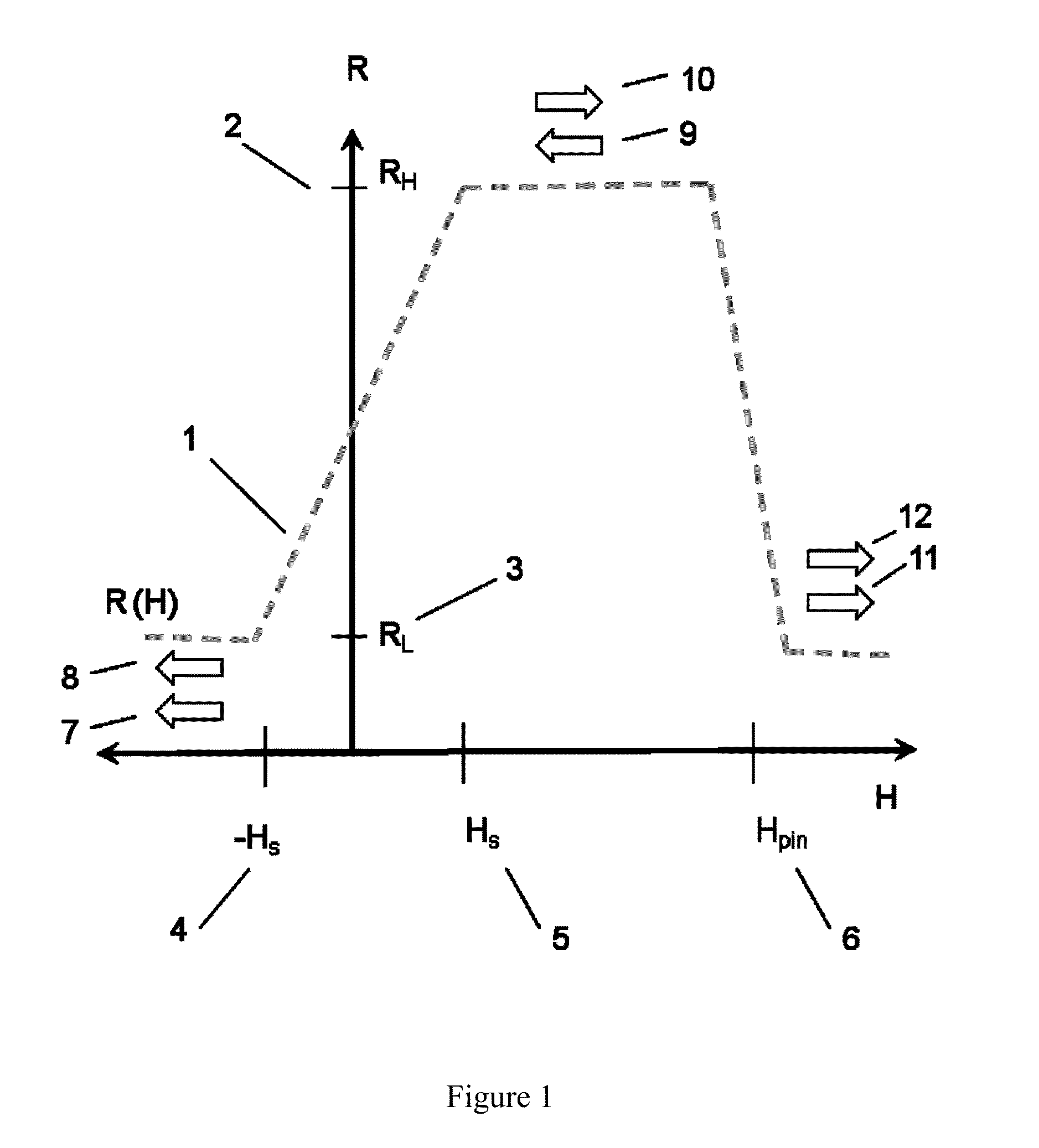
[0024]The sensor elements of the disclosed angle sensor are configured as spin valves, that is, they contain one magnetic layer this has a magnetization that is nominally fixed in orientation, often referred to as the reference layer, and another ferromagnetic layer that has a magnetization that is free to move in response to an applied magnetic field, normally called the free layer. The reference layer can be a single magnetic layer or a synthetic ferromagnetic structure, which is pinned by the pinning layer. In a MTJ element, the free layer and reference layer are separated by an insulating barrier, and electrical current tunnels through the barrier. In a GMR element, the free layer and the pinned layer are separated by a non-magnetic metallic layer. Electrical current can flow either in the plane of the GMR thin film or perpendicular to the plane.

[0025]The general form of the magnetoresistive transfer curve of a GMR or MTJ magnetic sensor element suitable magnetic field measureme...


PUM


Abstract

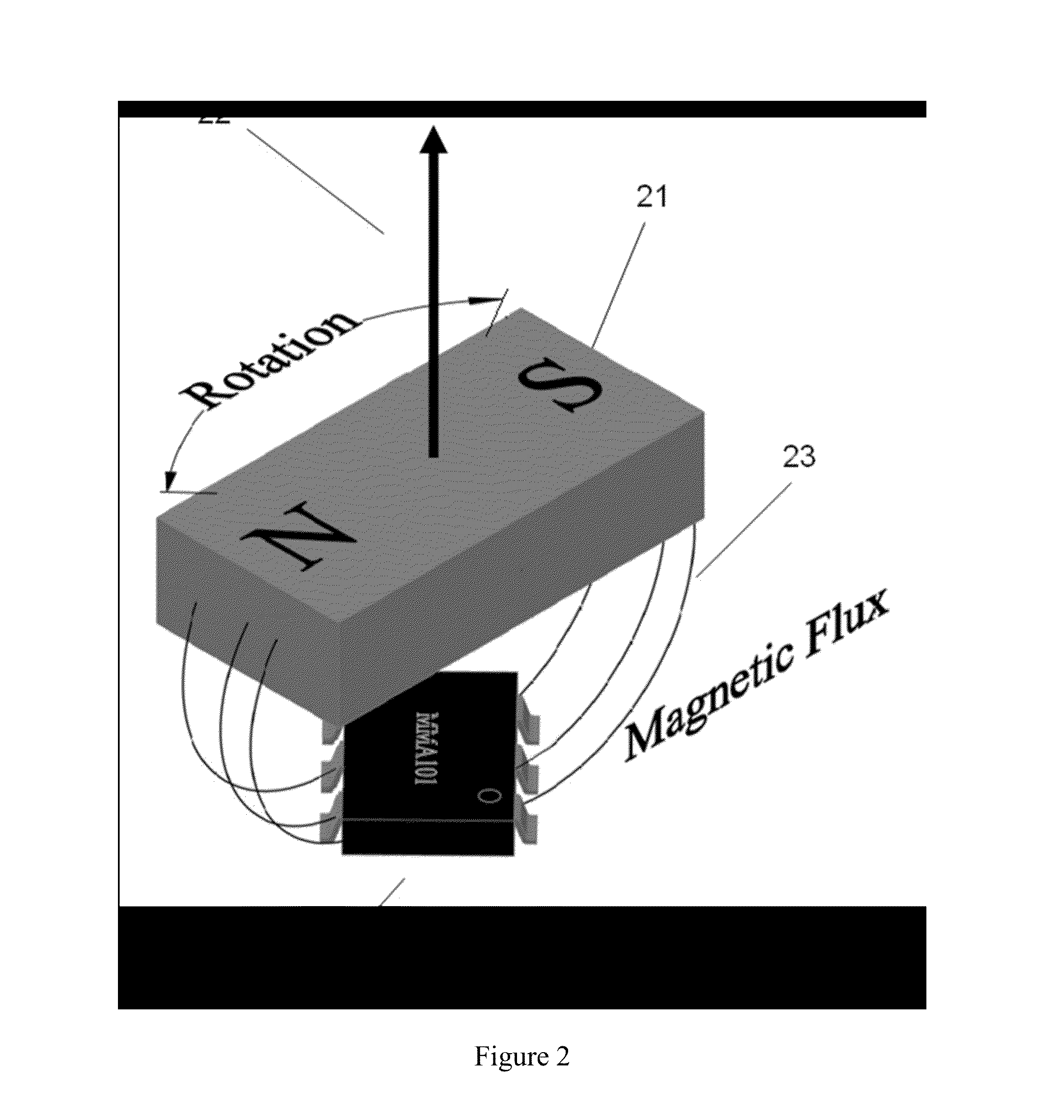
A single package magnetoresistive angle sensor for use in measuring rotation angle of a magnet is disclosed. The magnetoresistive angle sensor comprises a pair of magnetoresistive sensor chips, wherein one of the chips is rotated by 180-degree rotation relative to the other. The magnetoresistive sensor chips are attached to a standard semiconductor package lead frame to form a single-axis push-pull full-bridge sensor. Each of the magnetoresistive sensor chips comprises a pair of magnetoresistance sensor arms. Each magnetoresistive sensor arm comprises one or more GMR or MTJ sensor elements. The GMR of MTR sensor elements utilize a pined layer. The element blocks of the magnetoresistive sensor electrically are interconnected and connected to the package leads by wirebonding. The magnetoresistive angle sensor can be packaged into various standard semiconductor package designs. Also, provided is a dual-axis push-pull full-bridge magnetoresistive angle sensor comprised of two pairs of magnetoresistive sensor chips.

Description

CROSS-REFERENCE TO A RELATED APPLICATION[0001]This application is a 35 U.S.C. §371 national phase application of PCT / CN2012 / 071889, filed on Mar. 2, 2012, which claims priority to a Chinese Patent Application No. CN201110050704.6, filed on Mar. 3, 2011, incorporated herein by reference in its entirety.FIELD OF THE INVENTION[0002]The invention relates generally to single-package magnetoresistive angle sensors, with specific emphasis on magnetic field sensors used in combination with a permanent magnet in order to provide a non-contact measurement of rotation angle.BACKGROUND OF THE INVENTION[0003]Magnetic sensors in combination with a rotating magnet provide an attractive means for non-contact measurement of the orientation of rotating shafts in various automotive, industrial, and consumer applications. There are many different types of sensors in the prior art for measuring the orientation of a magnetic field. However, they all suffer from various limitations well known in the art, ...

Claims


Application Information

Patent Timeline
Patent Type & Authority Applications(United States)
IPC IPC(8): G01R33/09H10N50/10H10N50/80
CPCG01R33/098B82Y25/00G01B7/30G01R33/093G01D5/145H10N50/10
Inventor DEAK, JAMES G.SHEN, WEIFENGZHANG, XIAOJUNLEI, XIAOFENGJIN, INSIKXUE, SONGSHENG
Owner MULTIDIMENSION TECH CO LTD
Why Eureka
Eureka Blog
Learn More