
Battery parallel balancing circuit

a parallel balancing and battery technology, applied in the direction of charging equalisation circuit, transportation and packaging, battery pack section, etc., can solve the problems of reduced energy capacity of batteries or battery packs, complicated connection of multiple battery packs in parallel, and severe limitations in current control. , to achieve the effect of diffusing energy storage capacity

Active Publication Date: 2013-12-19
GM GLOBAL TECH OPERATIONS LLC
View PDF15 Cites 28 Cited by
  • Summary
  • Abstract
  • Description
  • Claims
  • Application Information

AI Technical Summary

Benefits of technology

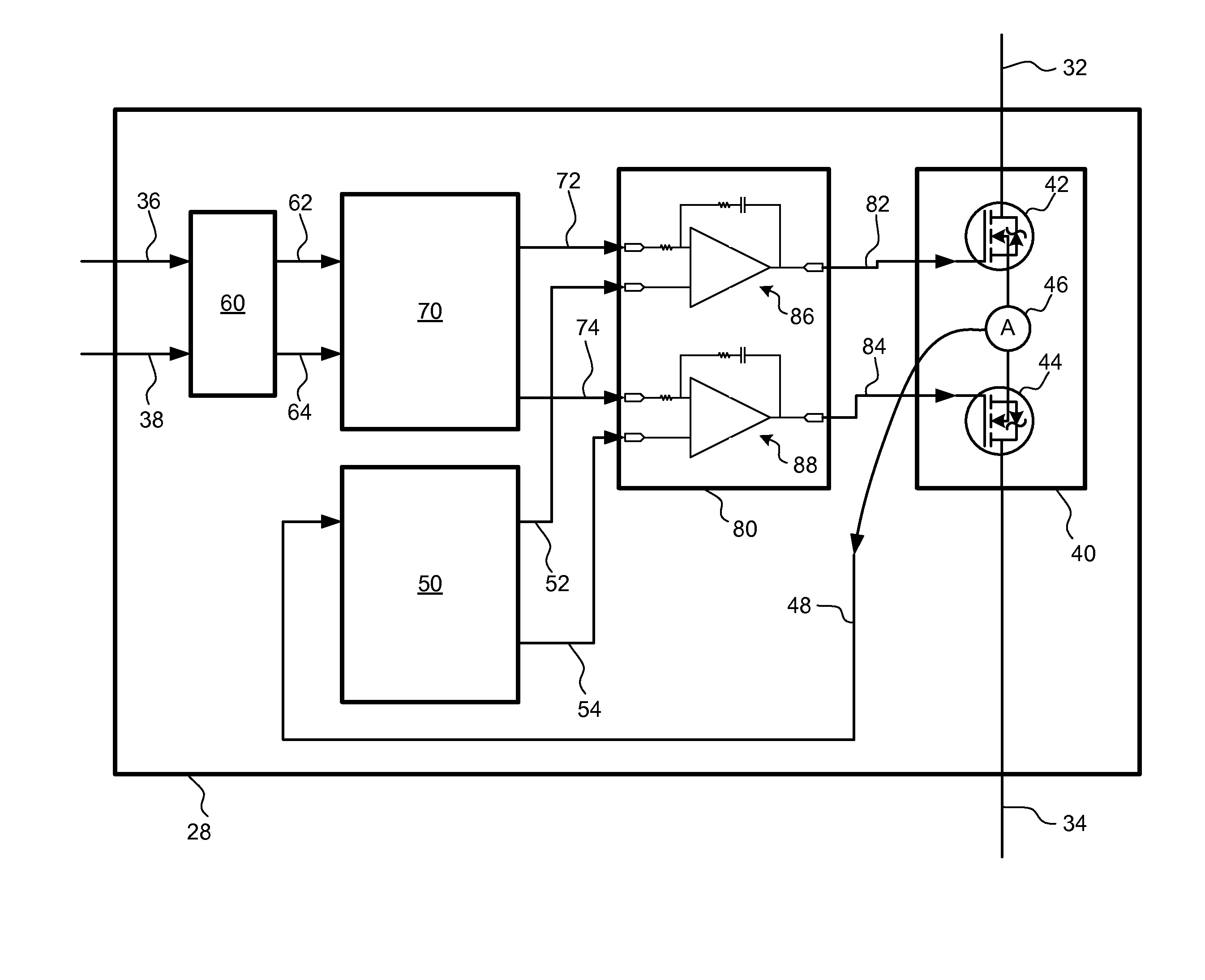
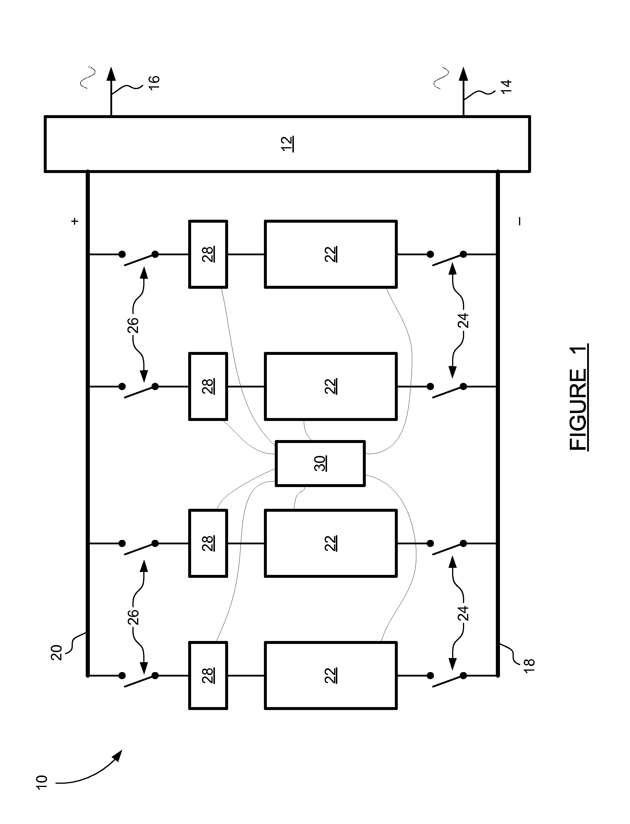
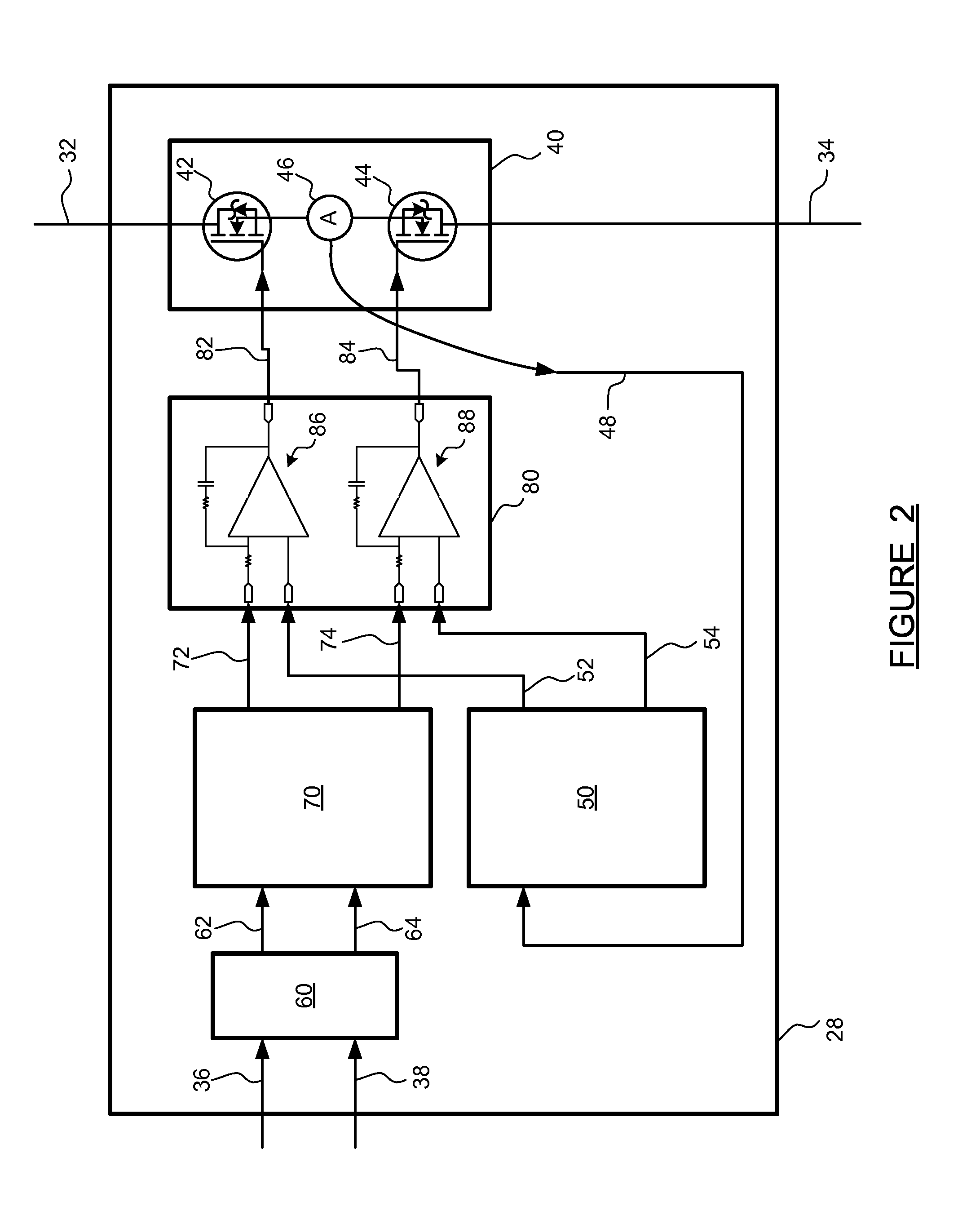
The present invention provides a method and device for regulating charging and discharging current through a battery pack. The invention involves connecting multiple battery packs in parallel to an inverter, which can use grid power to charge the battery packs or provide AC power through the inverter. A current balancing circuit is used to regulate the current through each battery pack to prevent excessive charging or discharging. The current balancing circuit includes two FETs arranged in series and in opposite directions, and a current sensor. The device uses proportional-integral control to provide a signal to the gates of the FETs, ensuring that the actual current flowing through the circuit is regulated to a target current value, which is determined to achieve balanced charging and discharging among the multiple battery packs.

Problems solved by technology

These battery packs or battery pack sections may have reduced energy capacity (state of health) relative to the capacity when they entered in-vehicle service.
Post-vehicle-life battery packs from electric vehicles can be used in CES systems, but the connection of multiple battery packs in parallel is complicated by variations in the state of health of sections of the battery packs.
This variation is problematic because multiple battery packs in parallel will charge and discharge at different rates if the battery packs have different capacities, which they are likely to have in a post-vehicle use scenario.
If current is not regulated, the differences in charging and discharging rates between the battery packs may cause excessive charging or discharging of some battery packs or cells, resulting in damage.
If the transistor is reverse biased, the amount of current it can control is severely limited.

Method used


Image

  • Battery parallel balancing circuit
  • Battery parallel balancing circuit
  • Battery parallel balancing circuit

Examples


Embodiment Construction

[0013]The following discussion of the embodiments of the invention directed to a battery parallel balancing circuit is merely exemplary in nature, and is in no way intended to limit the invention or its applications or uses.

[0014]Electric vehicles and engine / electric hybrid vehicles (hereinafter described simply as electric vehicles) are becoming increasingly popular and viable as various enabling technologies improve. One factor that all such vehicles have in common is the need for a high-capacity battery pack for energy storage. Eventually, a battery pack will have to be replaced in an electric vehicle, so the vehicle driving range can be maintained at an acceptable level. The post-vehicle-life battery pack may no longer be suitable for use in an electric vehicle, but still retains considerable energy storage capability. In order to use such battery packs effectively in post-vehicle applications such as Community Energy Storage, it would be beneficial to be able to manage charging...


PUM


Abstract

A method and device for regulating charging and discharging current through a battery pack. Two or more battery packs are connected in parallel to an inverter, such that the inverter can use grid power to charge the battery packs or the battery packs can provide AC power through the inverter. A current balancing circuit device is placed in series with each battery pack and is used to regulate the current through the battery pack so that none of the battery packs is excessively charged or discharged. The current balancing circuit includes two field effect transistors (FETs) arranged in series and in opposite directions, where one FET controls charging current and the other controls discharging current. The balancing circuit also includes a current sensor, and uses proportional-integral control to provide a signal to the FETs such that the actual current flowing through the circuit is regulated to a target current value.

Description

BACKGROUND OF THE INVENTION[0001]1. Field of the Invention[0002]This invention relates generally to a current regulating circuit and, more particularly, to a method and apparatus for regulating charging and discharging current between two or more parallel-connected battery packs having varying states of health or states of charge, where the apparatus includes no mechanical switches or relays and uses field effect transistors, a current sensor and a control stage to achieve a desired current through each of the parallel battery packs.[0003]2. Discussion of the Related Art[0004]Electric vehicles and gasoline- or diesel-electric hybrid vehicles are rapidly gaining popularity in today's automotive marketplace. Electric and hybrid vehicles offer several desirable features, such as reduced emissions, reduced usage of petroleum-based fuels, and potentially lower operating costs. A key component of both electric and hybrid vehicles is the battery pack. Battery packs in these vehicles typica...

Claims


Application Information

Patent Timeline
Patent Type & Authority Applications(United States)
IPC IPC(8): H02J7/00
CPCH02J7/0016Y02T10/70
Inventor REYNOLDS, MICHAEL G.NAMUDURI, CHANDRA S.KARLSON, PETER T.FOISY, DANIEL G.
Owner GM GLOBAL TECH OPERATIONS LLC
Learn More