Rotary electric machine driving system

a technology of electric motors and driving units, applied in the direction of electric generator control, dynamo-electric converter control, dynamo-electric gear control, etc., can solve the problems of increasing the size and cost of the control system that includes an inverter that is a rotary electric machine driving unit, and achieves the effect of increasing torque and preventing excessive curren

Inactive Publication Date: 2013-12-19
TOYOTA JIDOSHA KK
View PDF5 Cites 26 Cited by
  • Summary
  • Abstract
  • Description
  • Claims
  • Application Information

AI Technical Summary

Benefits of technology

[0017]With the rotary electric machine driving system according to the aspect of the invention, it is possible to implement the rotary electric machine that is able to increase torque even in a low rotation speed range while preventing excessive currents from flowing through the stator coils.

Problems solved by technology

However, the inventors found that, unless a method of superimposing pulse current is devised, the peak values of currents that flow through the stator coils become excessive and this may lead to inconvenience, such as an increase in size and cost of a control system that includes an inverter that is a rotary electric machine driving unit.

Method used


Image

  • Rotary electric machine driving system
  • Rotary electric machine driving system
  • Rotary electric machine driving system

Examples


Embodiment Construction

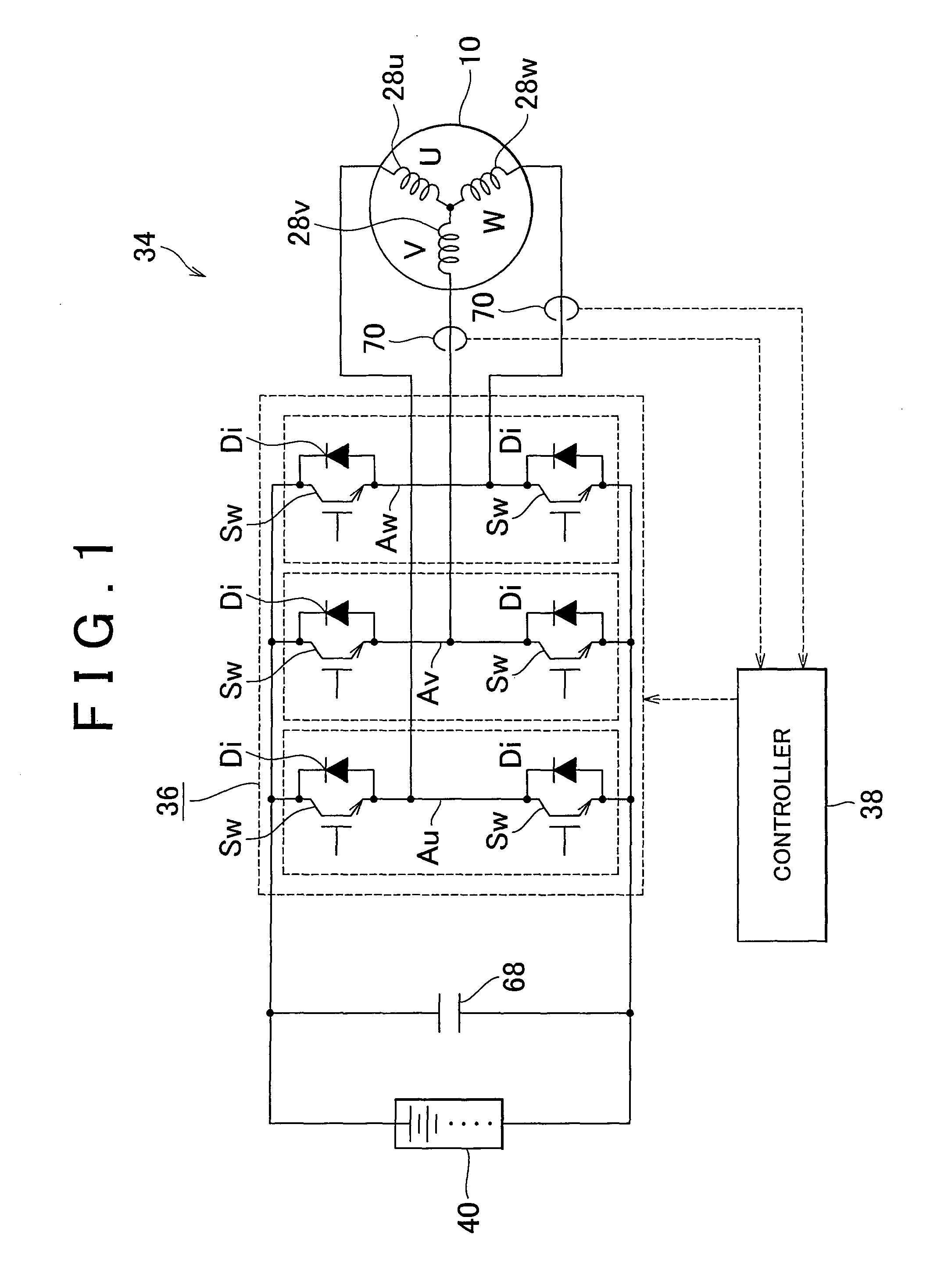
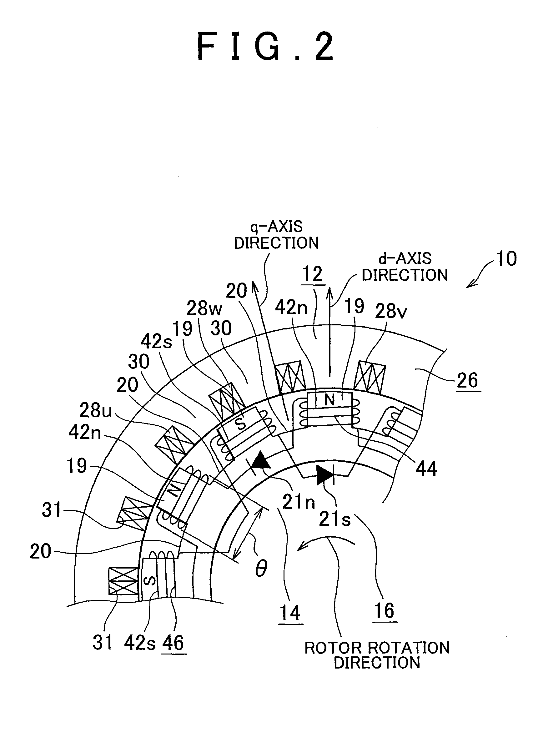
[0048]FIG. 1 to FIG. 6 are views that show an embodiment of the invention. FIG. 1 is a view that shows the schematic configuration of a rotary electric machine driving system according to the embodiment. FIG. 2 is a schematic view that partially shows a portion at which a stator faces a rotor in the embodiment. FIG. 3A is a schematic view that shows a state where a magnetic flux passes through the rotor in the embodiment. FIG. 3B is a graph that shows the result obtained by calculating the amplitude of a magnetic flux that links with a rotor coil while varying the width θ of the rotor coil in the circumferential direction in the rotary electric machine shown in FIG. 2. FIG. 4 is a block diagram that shows the configuration of a controller in the embodiment. As shown in FIG. 1, a rotary electric machine driving system 34 according to the embodiment includes a rotary electric machine 10, an inverter 36, a controller 38 and an electrical storage device 40. The inverter 36 is a driving ...


PUM


Abstract

A stator has multi-phase stator coils that are wound around a stator core by concentrated winding. A rotor has rotor coils that are wound at multiple portions of a rotor core in the circumferential direction and diodes that serve as rectifier unit that is connected to the rotor coils and that varies the magnetic characteristics of the respective rotor coils alternately in the circumferential direction. A rotary electric machine driving system includes a decreasing pulse superimposing unit that superimposes decreasing pulse current for a pulse-shaped decrease on a q-axis current command for passing currents through the stator coils.

Description

BACKGROUND OF THE INVENTION[0001]1. Field of the Invention[0002]The invention relates to a rotary electric machine driving system that includes a rotary electric machine having a stator and a rotor that are arranged to face each other, a driving unit that drives the rotary electric machine and a control unit that controls the driving unit.[0003]2. Description of Related Art[0004]As is described in Japanese Patent Application Publication No. 2009-112091 (JP-A-2009-112091), there is known a rotary electric machine in which rotor coils are provided for a rotor and induced currents are generated in the rotor coils by a revolving magnetic field to cause the rotor to generate torque. The revolving magnetic field is generated by a stator, and includes space harmonics. In addition, with this rotary electric machine, induced currents are efficiently generated in the rotor coils to make it possible to obtain the effect of efficiently increasing torque that acts on the rotor. FIG. 21 to FIG. 2...

Claims


Application Information

Patent Timeline
Patent Type & Authority Applications(United States)
IPC IPC(8): H02K11/00H02P21/00H02P21/22H02P27/04
CPCH02K19/10H02K11/0073H02P25/026H02P21/0003H02K19/12H02K21/042H02P21/04H02P25/03
Inventor YAMADA, EIJIMIZUTANI, RYOJIHIRAMOTO, KENJINAKAI, HIDEOMINOSHIMA, NORIMOTO
Owner TOYOTA JIDOSHA KK
Why Eureka
Try Eureka