Eureka AIR delivers breakthrough ideas for toughest innovation challenges, trusted by R&D personnel around the world.

Non-inflation adapter for prompt engagement with a shank of a screw driver and a handle

Inactive Publication Date: 2005-10-11
HUANG DANIEL
View PDF11 Cites 66 Cited by
  • Summary
  • Abstract
  • Description
  • Claims
  • Application Information

AI Technical Summary

Benefits of technology

[0010]The present invention has a main object to provide an adapter for prompt engagement a shank of screw driver with a handle into which the shank of a screw driver is readily to engaged without application of the sleeve. It is convenient and don't have to use one hand to perform two actions synchronously.
[0011]Another object of the present invention is to provide an adapter for prompt engagement a shank of screw driver with a handle which is structurally integrated and readily to assemble to promote the torque force.
[0012]Still another object of the present invention is to provide an adapter for prompt engagement a shank of screw driver with a handle from which the shank rebounds out will temporarily stopped in the rim of the central bore without hurting people.

Problems solved by technology

This type of adapter 10 gives great inconvenience to user because the user has to use one hand to the synchronously perform two actions.
This arrangement is very skillfully and convenient, but don't suitable to engage a shank of a screwdriver.
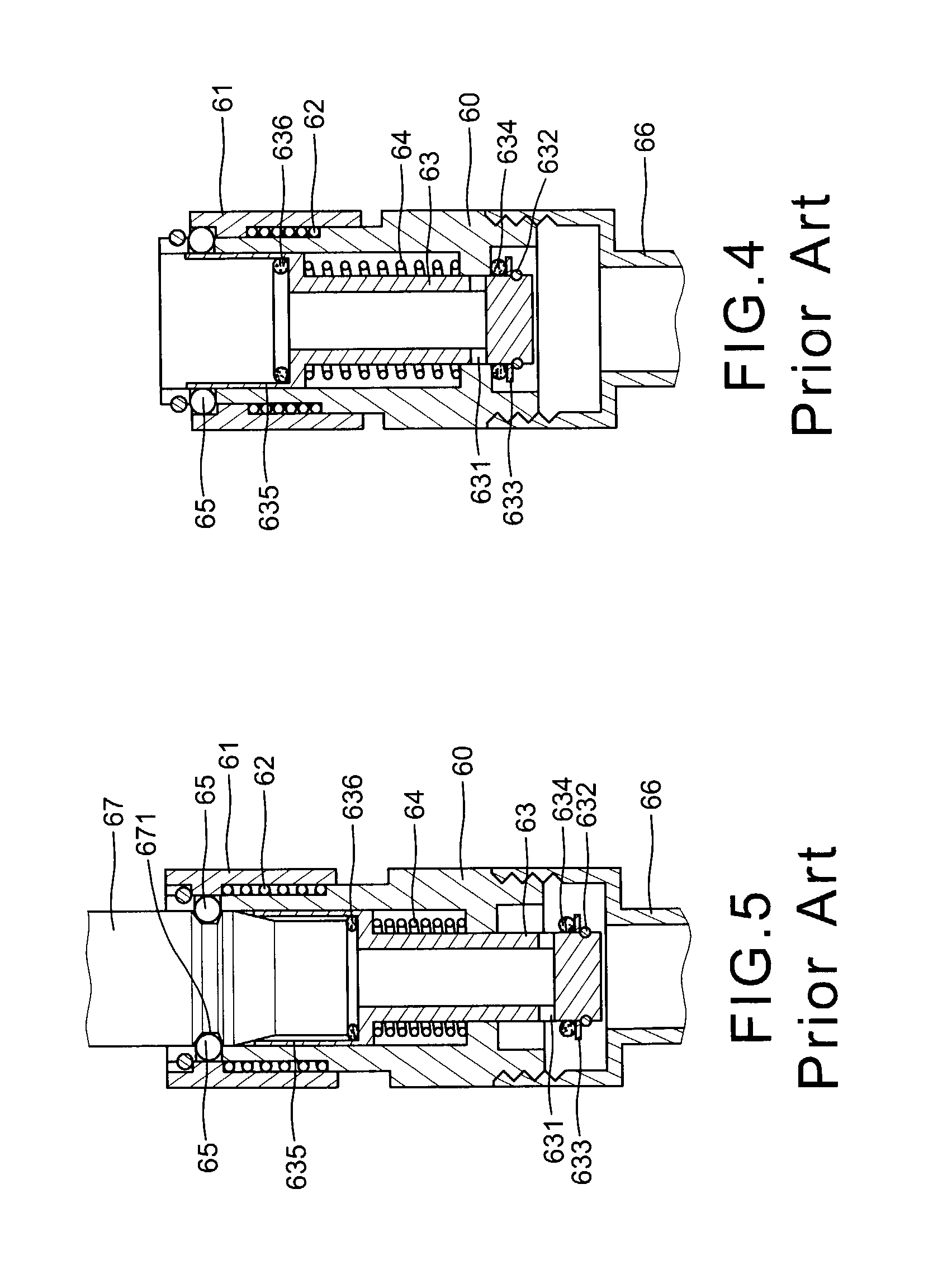
However, it has at least the following disadvantages:a) the resilient force of the spring 77 is too strong, when inserts the shank into the central bore 71, it may be rebound out to hurt people,b) it requires more parts, the assembly of the parts is complicated and cost more,c) the inverse U-shaped member 78 is not integrated with the tubular body but is punched to connect the tubular body, so the torque is therefore weak,d) the lower end of the spring 77 is freely disposed on the top of the inverse U-shaped member 78, it may be inclined toward one side and deformed that affect its resilient force, ande) the central bore 71 has an enlarged bottom that affect its intensity.

Method used


Image

  • Non-inflation adapter for prompt engagement with a shank of a screw driver and a handle
  • Non-inflation adapter for prompt engagement with a shank of a screw driver and a handle
  • Non-inflation adapter for prompt engagement with a shank of a screw driver and a handle

Examples


Embodiment Construction

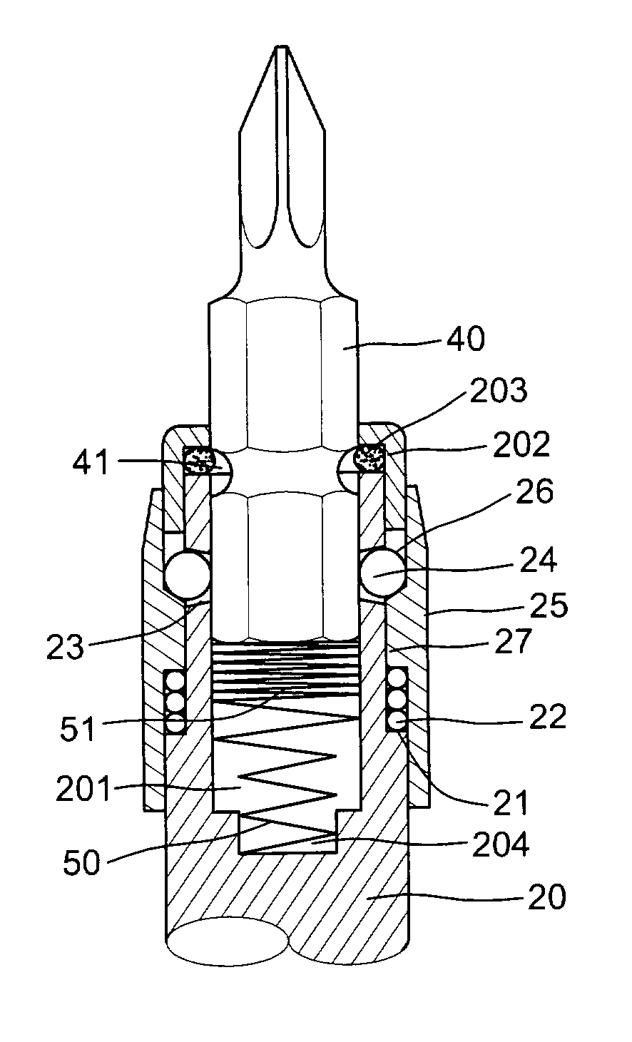
[0030]As illustrated in FIGS. 7, 8 and 9 of the drawings, the first embodiment of the an adapter for prompt engagement a shank of screw driver with a handle of the present invention comprises a hollow interior tubular adapter 20 which has a rear end enabling to connected a handle (not shown), a concaved front outer periphery defined a shoulder 21, a plurality of conical through holes 23 spacedly formed around a middle peripheral wall of the concaved front out periphery for respectively disposing a plurality of steel balls 24, an annular sleeve 25 slidably wrapped on the concaved front outer periphery including an annular convex 27 on a middle inner periphery thereof biased by a spring means 22 and having a sloped upper surface, a polygonal central bore 201 including a reduced bottom 204, a conical spring 50 disposed into the polygonal central bore 201 including a thick larger upper portion 51 at a position preventing the steel balls from entered into the central bore 201 and an inco...


PUM


Abstract

An adapter for prompt engagement a shank of screw driver with a handle includes a tubular adapter connected with a handle, a polygonal central bore having a reduced bottom, a concaved front outer periphery to define a shoulder thereunder, a plurality of conical through holes around a middle peripheral wall for respectively disposing a plurality of steel balls, a conical spring disposed into the central bore having a large thick upper portion blocking the conical through holes and a small incompact lower portion fixed in the reduced bottom, an annular sleeve with an annular convex on middle inner periphery slidably wrapped on the adapter biased by a circular spring on the shoulder, an annular cap fixed on the top of the adapter with a circular ring engaged therebetween, a receiving space for receiving the steel balls and a polygonal shank of in the bore is held by the steel balls.

Description

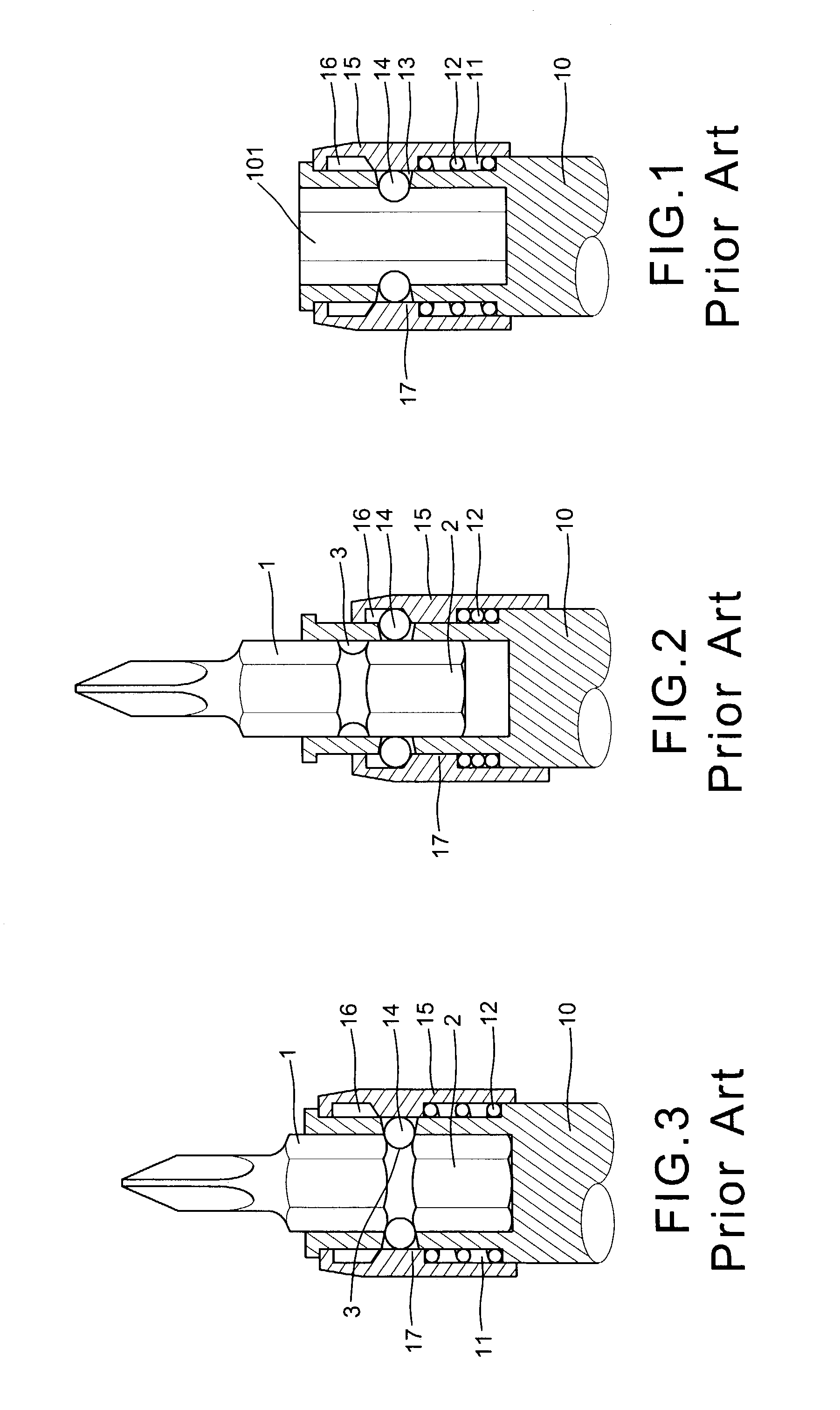
BACKGROUND OF THE INVENTION[0001]The present invention relates to screw drivers and more particularly to an adapter for prompt engagement a shank of screw driver with a handle into which the shank of the screw driver is readily engaged.[0002]A prior art adapter 10 (as shown FIGS. 1, 2 and 3) which has a rear end connected to a handle (not shown), a polygonal central bore 101 in the front end, a concaved outer periphery 11 wrapped with a spring 12, a plurality of conical through holes 13 spacedly formed around a central portion of the concaved periphery for respectively disposing a plurality steel ball 14 therein, an annular sleeve 15 slidably sleeved on the concaved outer periphery 11 having an annular convex 17 biased by the spring 12 including a sloped upper surface and a receiving space 16 above the sloped upper surface to receiving the steel balls 14 when they move outward. A polygonal shank 1 of a screw driver has a plurality of the semi-circular grooves 3 spacedly formed aroun...

Claims


Application Information

Patent Timeline
IPC IPC(8): B23B31/10B23B31/107B25B23/00
CPCB23B31/1071B25B23/0035B23B2260/136Y10T279/3481Y10S279/906Y10T279/17752
Inventor HUANG, DANIEL
Owner HUANG DANIEL
Why Eureka
Eureka Blog
Learn More