
Underwater Connector Arrangement

a technology of connectors and connectors, applied in the direction of subaqueous/subterranean adaption, antenna details, antennas, etc., can solve the problems of affecting the sealing integrity, affecting the sealing, and affecting the operation of the equipment, so as to reduce or avoid such interference, reduce the physical size of components, and avoid the effect of data signal interferen

Active Publication Date: 2013-12-05
WISUB
View PDF8 Cites 23 Cited by
  • Summary
  • Abstract
  • Description
  • Claims
  • Application Information

AI Technical Summary

Benefits of technology

This patent describes a system for transmitting data wirelessly in air and underwater. The system uses existing protocols like WiFi, GSM, Bluetooth, GPRS, CDMA and Zigbee, making it easy to use existing software. The system also includes a power transfer arrangement for transmitting electrical power between components. The components are small in size, so care needs to be taken in the placement of the antenna and power transfer parts to avoid interference. The system also includes an encapsulation material to prevent water from coming into direct contact with electronic and / or electrical parts. The technical effects of this patent include improved wireless data transmission and simplified maintenance and inspection operations.

Problems solved by technology

Such aforementioned environments are harsh and technical apparatus failure can be costly to address.
Moreover, ocean salt water is highly corrosive and conductive, which creates difficulties when undersea connections are being made.
So whilst direct physical connections between conductors is a straightforward way of connecting cables, they face particular challenges when used underwater, particularly when it is necessary to separate and reconnect them underwater multiple times since this can adversely affect sealing integrity and so risk water ingress.
Physical connections can also be hard to align accurately and are more restrictive in their ability to accommodate tight bending.

Method used


Image

  • Underwater Connector Arrangement
  • Underwater Connector Arrangement
  • Underwater Connector Arrangement

Examples


Embodiment Construction

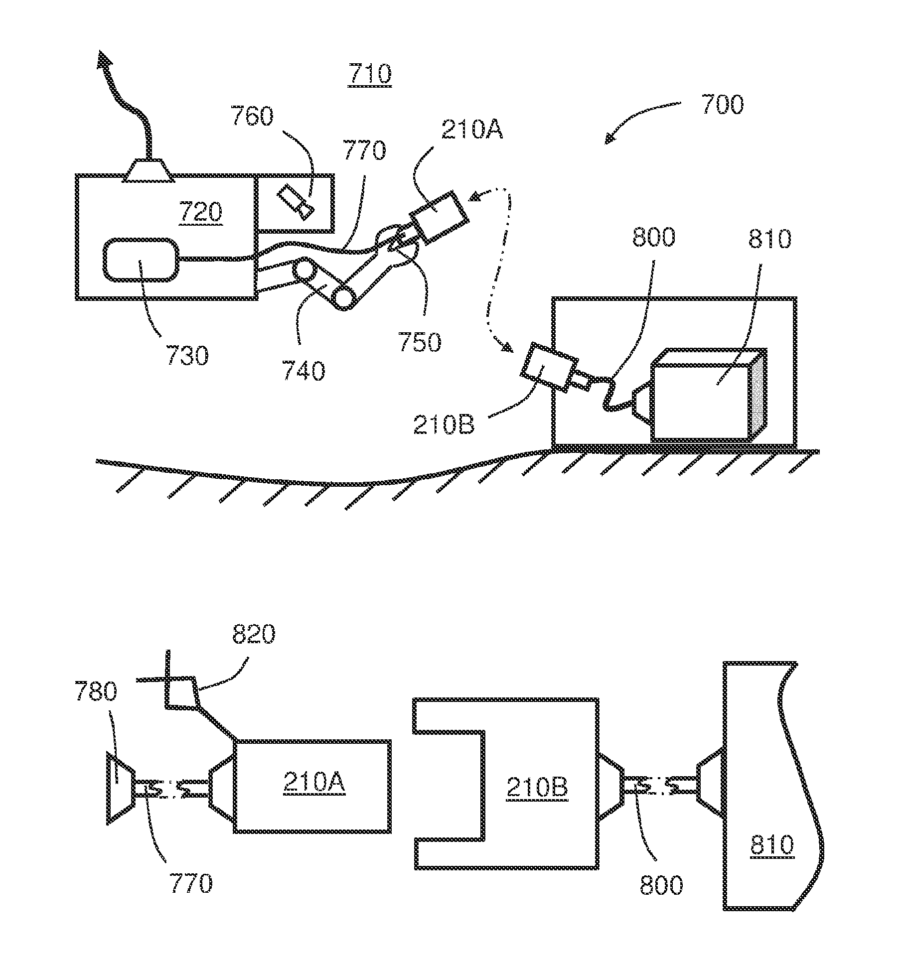
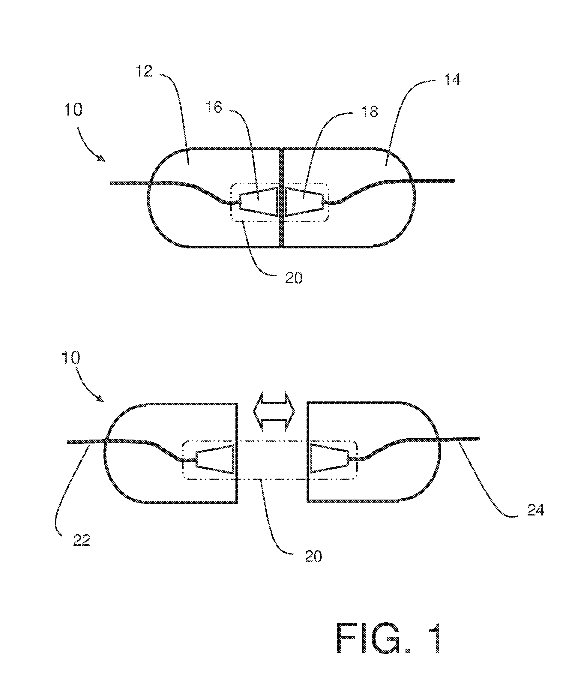
[0067]Referring to FIG. 1, an underwater connector arrangement 10 is shown which is suitable for being used in sub-sea environments. This comprises two components 12, 14, each of which comprises a respective non-coil antenna 16, 18 which is designed to be able to transmit and receive radiating or propagating microwaves or millimetre waves which might, depending on the application, be somewhere in the range of 300 MHz to 300 GHz. The antennae 16, 18 together form a wireless data connection 20 which allows data to be passed between the components 12, 14 and thereby connect respective attached cables 22, 24. The antennae 16, 18 are received in submersible encapsulations, the maximum dimensions of which are at least one eighth of the wavelength (or the minimum wavelength if the wavelength varies) of the carrier waves.

[0068]As shown in the lower part of FIG. 1, the wireless data connection may be maintained even when the two components 12, 14 are not in physical contact with one another ...


PUM


Abstract

An underwater connector includes a first component and a second component, wherein the components are operable to be coupled together in operation in a first coupled state, and operable to be mutually spatially separated in a second uncoupled state. The first and second components each include communication arrangements which are operable to provide wireless communication between the first and second components when in their first coupled state. The first and second components include a power transfer arrangement for transmitting power between the first and second components. The power transfer arrangement includes inductive coupling devices and / or capacitive coupling devices, wherein the power transfer arrangement is implemented substantially as an annulus, for example circular, elliptical, or polygonal, on the first and second components together with the communication arrangements being disposed within the annulus and / or around a periphery of the annulus. The wireless communication is operable to occur using a wireless signal whose carrier frequency is within a frequency range of 300 MHz to 300 GHz, wherein the wireless communication is implemented using microwave and millimeter wave technologies.

Description

CROSS REFERENCE TO RELATED APPLICATION(S)[0001]This application is a §317 U.S. National Phase of International Application Serial No. PCT / EP2012 / 052873 filed Feb. 20, 2012, which is turn claims priority to Norwegian Application Serial No: 20110292 filed Feb. 21, 201. The entire disclosure of all the above documents is herein incorporated by reference.BACKGROUND[0002]1. Field of the Invention[0003]The present invention relates to underwater connector arrangements, for example underwater connector arrangements which are operable to provide wide-bandwidth signal transfer between two underwater objects without necessarily requiring a physical connection between them. Moreover, the present invention also concerns methods of transferring wide-bandwidth signals via underwater connector arrangements.[0004]2. Description of Related Art[0005]There is an increasing trend for deploying technical apparatus within ocean environments, for example associated with offshore exploration and production...

Claims


Application Information

Patent Timeline
IPC IPC(8): H01Q1/04
CPCH01Q1/04H04B13/02H04B5/22H04B5/72H04B5/24H04B5/79H01Q1/2291
Inventor BOKENFOHR, MARKCIAMULSKI, TOMASZ
Owner WISUB
Learn More