
Addititve manufacturing of components for downhole wireline, tubing and drill pipe conveyed tools

a technology of additive manufacturing and wireline, which is applied in the direction of additive manufacturing, computer aided design, instruments, etc., can solve the problems of complex routing and multiple passages, complicated machining and assembly, and not unique to electronics and sensors, and achieves the effect of reducing the number of conduits or channels, reducing the number of parts, and improving the quality of the produ

Inactive Publication Date: 2013-11-21
SCHLUMBERGER TECH CORP
View PDF8 Cites 50 Cited by
  • Summary
  • Abstract
  • Description
  • Claims
  • Application Information

AI Technical Summary

Benefits of technology

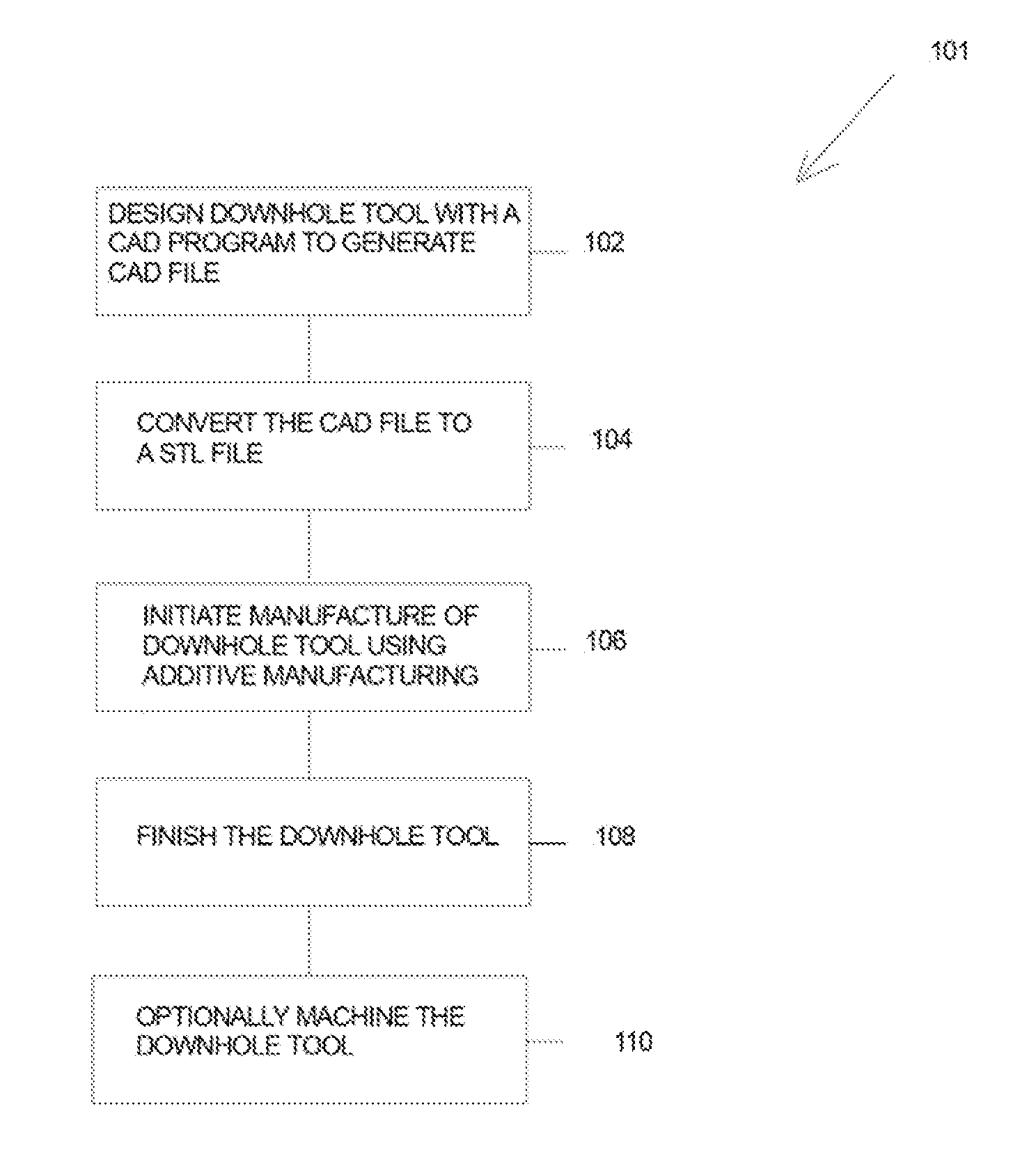
The patent text describes a method for manufacturing downhole components using an additive manufacturing technique. This involves designing a component with a computer program, converting the design to a STL file, and initiating manufacture of the downhole component using an additive manufacturing technique such as selective laser sintering or fused deposition. The finished downhole component is then finished to a desired shape and inspected. The technical effect of this method is the ability to manufacture complex downhole components with improved efficiency and accuracy.

Problems solved by technology

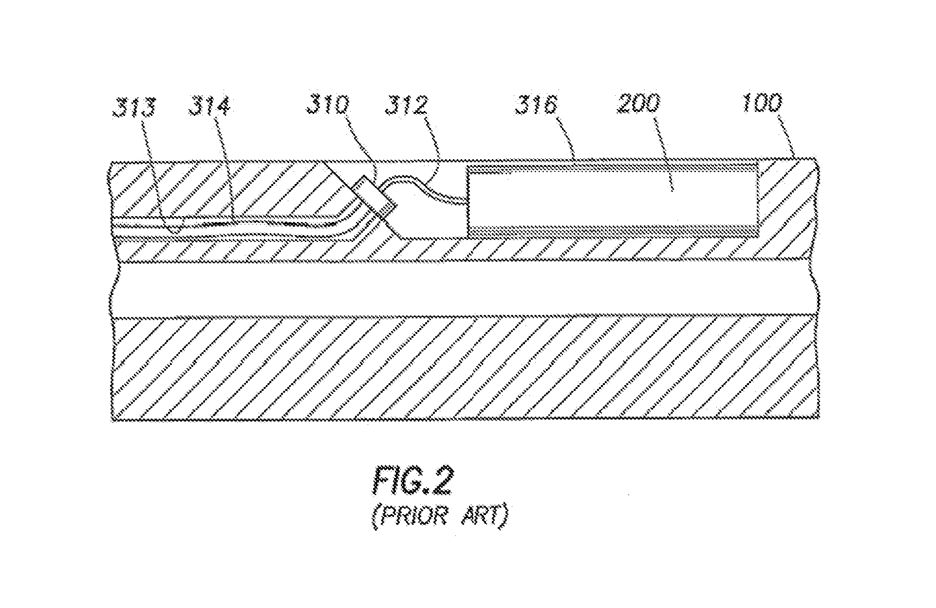
With this methodology, a more complex system requires more complex routing and multiple passages to make elaborate turns or form desired angles within the wall or body of the structure.
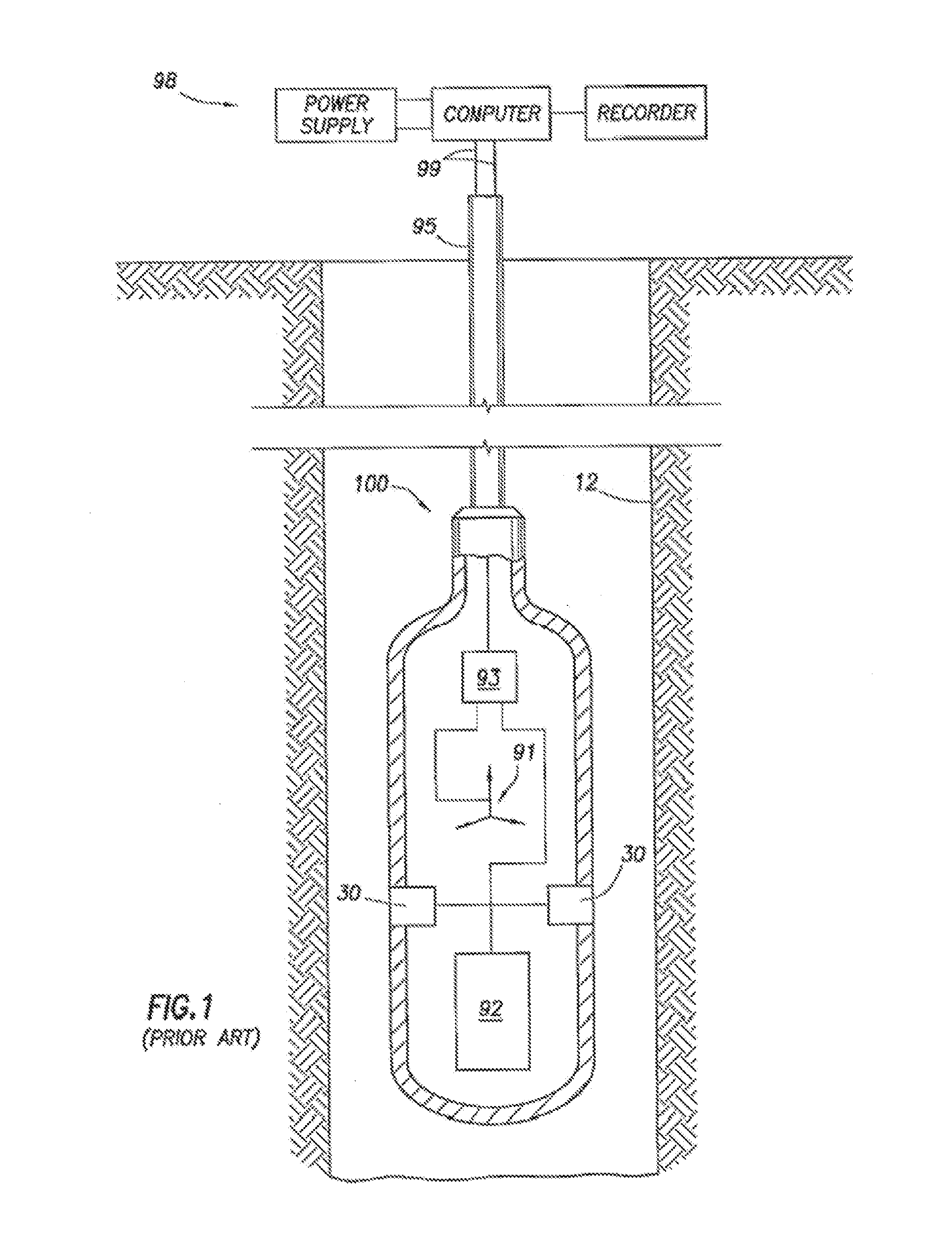
As a result, complicated machining and assembly may be required to form the passages enclosed by the tool 100.
However, the need for conduits or channels are not unique to electronics and sensors.

Method used


Image

  • Addititve manufacturing of components for downhole wireline, tubing and drill pipe conveyed tools
  • Addititve manufacturing of components for downhole wireline, tubing and drill pipe conveyed tools
  • Addititve manufacturing of components for downhole wireline, tubing and drill pipe conveyed tools

Examples


Embodiment Construction

[0031]The present disclosure generally relates to a method of manufacturing a component. While the disclosure details a manufacturing method related to an oilfield tool, a person having ordinary skill in the art will appreciate that the teachings of the disclosure are applicable to many industries outside the oilfield industry.

[0032]The present disclosure sets forth example embodiments for using additive manufacturing to manufacture components of downhole tools conveyed by downhole wireline, tubing, drill pipe and / or the like. A method in accordance with one or more aspects of the disclosure, uses starting materials to incorporate one or more feedthroughs, passages, channels, chambers and the like in a downhole tool structure during the formation of the structure. Downhole tool is used herein to include a portion of a tool or a complete tool that may be used in or about a wellbore or wellsite.

[0033]Stereo lithography (SLA), selective laser sintering (SLS), fused deposition modeling ...


PUM


Abstract

Additive manufacturing may be used to manufacture components of downhole tools conveyed by downhole wireline, tubing, drill pipe and / or the like. A method in accordance with one or more aspects of the disclosure uses starting materials to incorporate one or more feedthroughs, passages, channels, chambers and the like in a downhole tool structure during the formation of the structure. A CAD may be made and then converted to a STL file, and then stereo lithography, selective laser sintering, fused deposition modeling, direct metal laser sintering and / or electron beam melting may be used to form the downhole tool. Subtractive manufacturing may be performed on the downhole tool after the downhole tool is formed by additive manufacturing.

Description

CROSS-REFERENCE TO RELATED APPLICATIONS[0001]This application claims priority to U.S. Provisional Application 61 / 637,062 filed May 15, 2012, the entirety of which is incorporated herein by reference.FIELD OF THE INVENTION[0002]Aspects relate to manufacturing of industrial components. More specific aspects relates to a methodology for manufacturing parts, tools, instruments, components and equipment.BACKGROUND INFORMATION[0003]The methodology for manufacturing parts, tools, instruments, components or equipment has may entail an assembly or construction process. In the case of metallic apparatus, the parts have traditionally been formed in a casting or founding process. In the oil and gas industry, for example, tools for downhole use are formed as metallic cylinders that are used to house various types of sources, sensors, measurement equipment, sampling chambers, transmitters and the like.[0004]For example, downhole tools are used in drilling wells, investigating the subsurface forma...

Claims


Application Information

Patent Timeline
IPC IPC(8): G06F17/50
CPCG06F17/50B22F5/106B22F2998/10B33Y80/00Y02P10/25B22F10/25B22F10/66B22F10/28B22F10/12B22F2003/247B22F10/20G06F30/00
Inventor INTRIAGO VELEZ, JUAN CARLOS
Owner SCHLUMBERGER TECH CORP
Learn More