
Power transmitter and method for detecting non-intended object of power reception

a power transmitter and non-intended object technology, applied in the direction of batteries, exchanging data chargers, inductances, etc., can solve the problems of difficult to detect, difficult to detect no consideration is given to a method for sensing a non-intended object of power reception, etc., to achieve efficient detection of a non-intended object

Active Publication Date: 2013-11-07
SAMSUNG ELECTRONICS CO LTD
View PDF16 Cites 42 Cited by
  • Summary
  • Abstract
  • Description
  • Claims
  • Application Information

AI Technical Summary

Benefits of technology

The present invention is designed to solve the problem of power transmission in a wireless system when there are non-intended objects in the way. The invention provides a power transmitter and a method to detect these objects and prevent them from using the power. This results in more efficient and reliable power transmission.

Problems solved by technology

However, it is difficult to determine that failing to receive the ID authentication frame by the power transmitter is regarded as sensing the invalid receiver or the invalid materials.
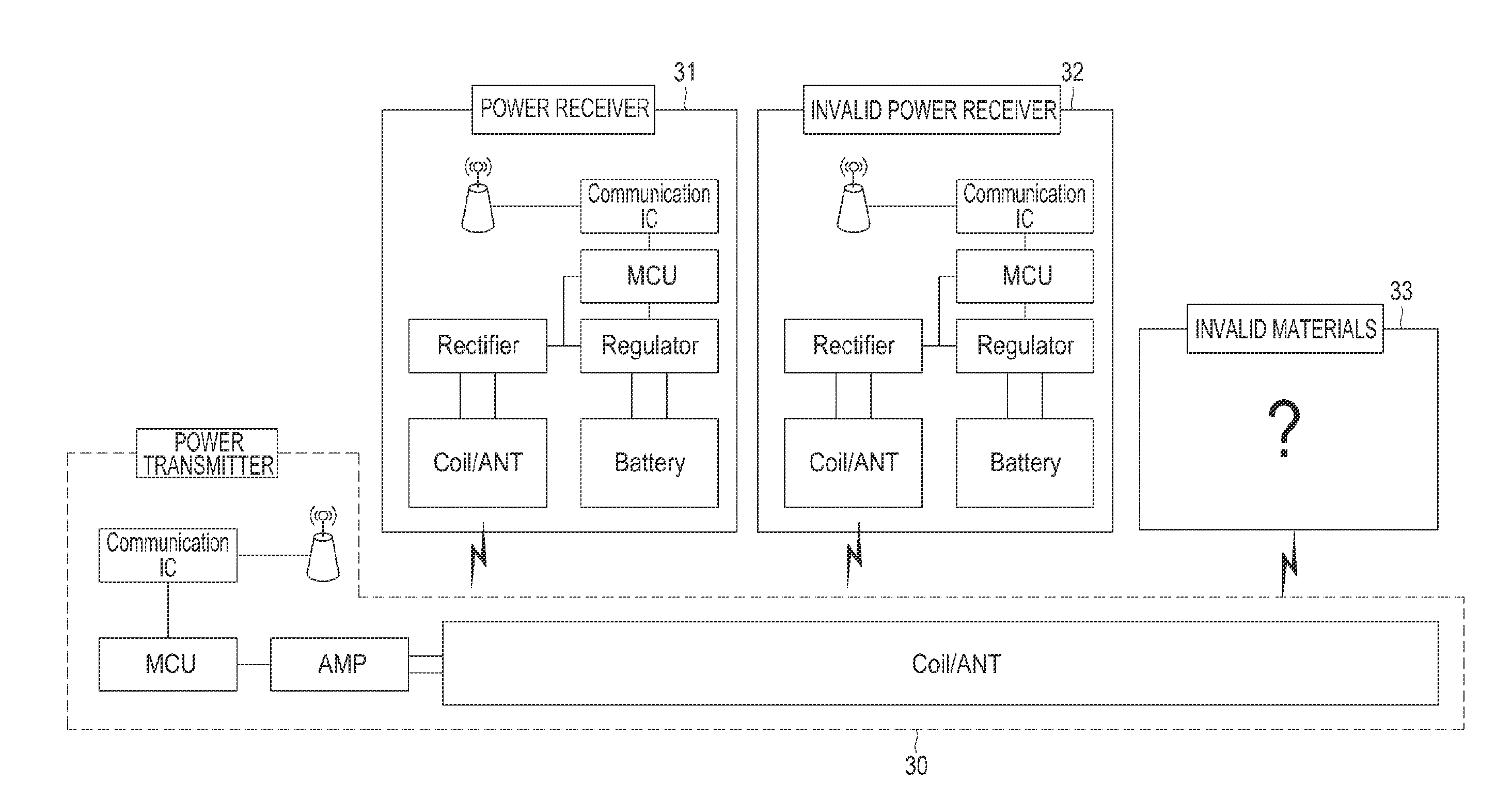
Accordingly, when the power receiver and the invalid materials are simultaneously placed on a charging deck, it is difficult to detect a non-intended object of power reception.
However, no consideration is given to a method for sensing a non-intended object of power reception in an environment for wirelessly transmitting power to multiple objects.
In the case of an abnormal condition, for example, when invalid materials such as an invalid power receiver and invalid metallic materials are located within a charging area, in the environment for wirelessly transmitting power as described above, there may occur unintended events, such as, for example, failure and overheating, which are caused by power loss / overload.

Method used


Image

  • Power transmitter and method for detecting non-intended object of power reception
  • Power transmitter and method for detecting non-intended object of power reception
  • Power transmitter and method for detecting non-intended object of power reception

Examples


Embodiment Construction

[0024]Embodiments of the present invention are described in detail with reference to the accompanying drawings. The same or similar components may be designated by the same or similar reference numerals although they are illustrated in different drawings. Detailed descriptions of constructions or processes known in the art may be omitted to avoid obscuring obscure the subject matter of the present invention.

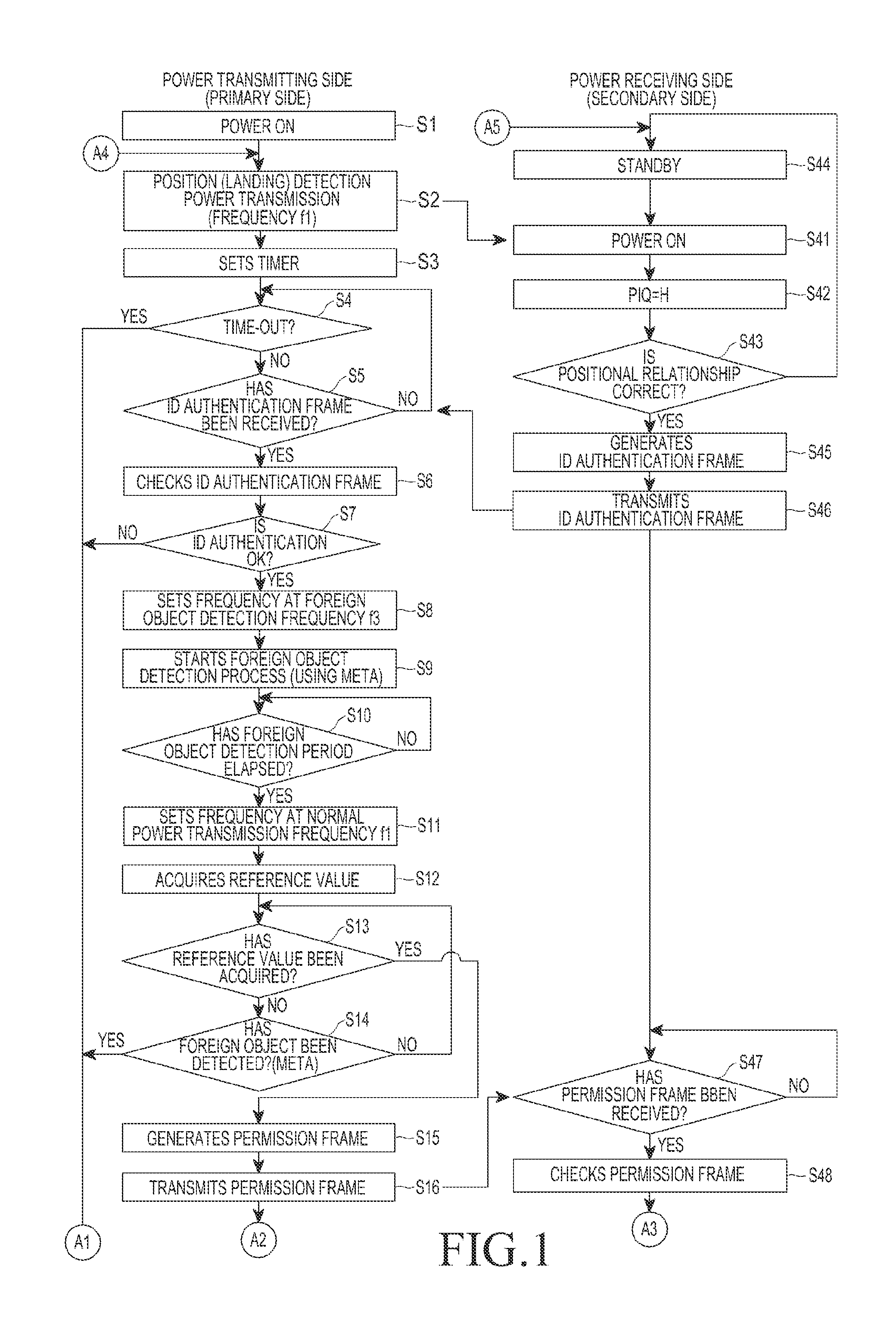
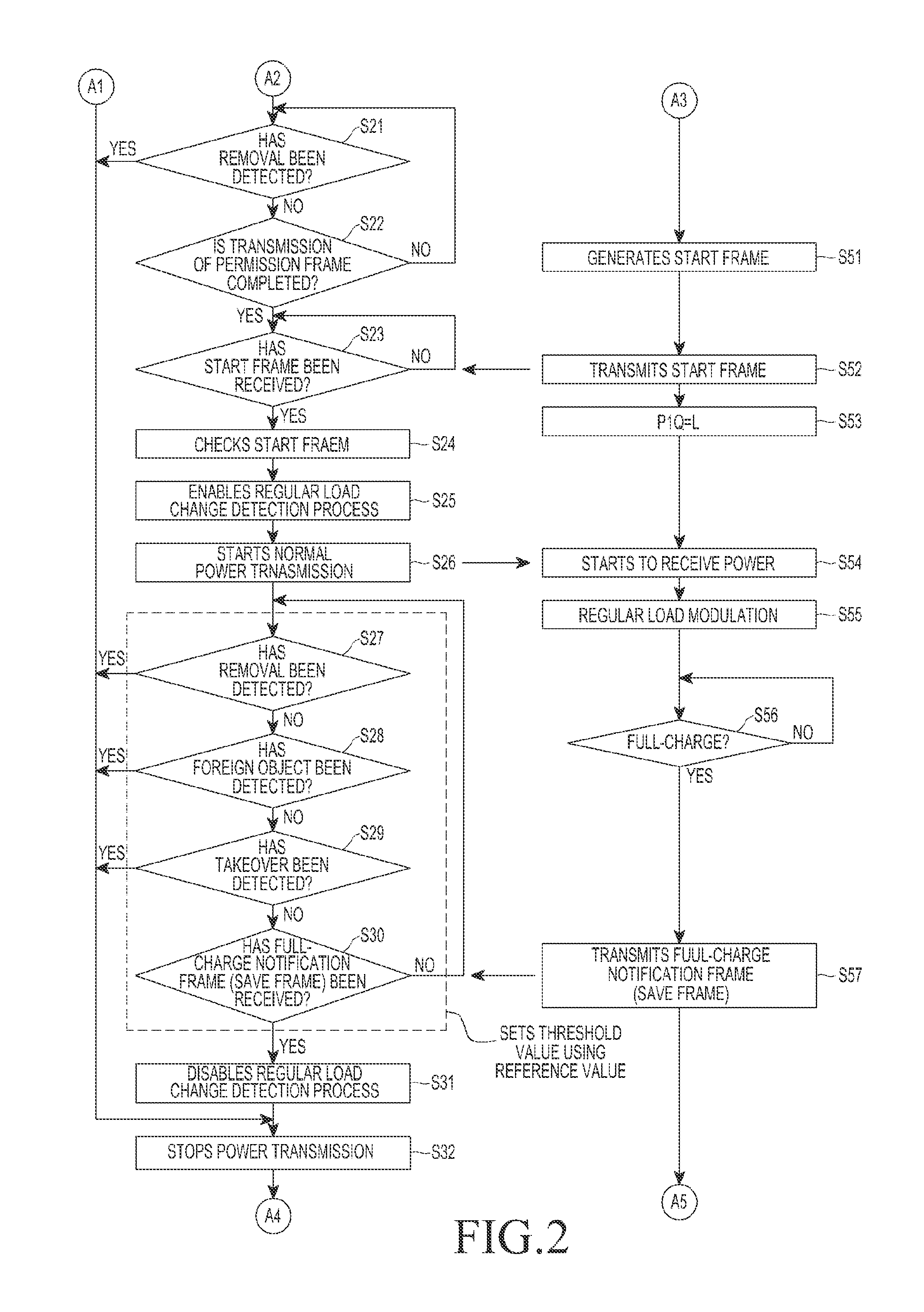
[0025]Embodiments of the present invention provide a method for detecting a non-intended object of power reception in a system for wirelessly transmitting power to multiple objects. A power transmitter determines whether an authentication request message is received in response to power transmission for communication, when the power transmitter senses a load change. The power transmitter determines whether the load change is within a predetermined range, based on initial information of a power receiver included in the authentication request message, when the authentication reques...


PUM

PropertyMeasurementUnit
impedanceaaaaaaaaaa
output poweraaaaaaaaaa

Abstract

Methods and apparatus are provided for detecting a non-intended object of power reception by a power transmitter. Power transmission for communication is performed, when the load change is sensed that has a value greater than or equal to a predetermined threshold. It is determined whether a subscription request, for subscribing to a network is received within a predetermined time period. The power transmission for communication is stopped when the subscription request is not received within the predetermined time period. Power is transmitted to a power receiver that has transmitted the subscription request, when the subscription request is received within the predetermined time period. It is determined whether a leakage power value exceeds an allowable range, when the power state report is received from the power receiver. The transmission of the power to the power receiver is stopped, when the leakage power value exceeds the allowable range.

Description

PRIORITY[0001]This application claims priority under 35 U.S.C. §119(a) to Korean Patent Application Serial No. 10-2012-0046524, which was filed in the Korean Intellectual Property Office on May 2, 2012, the contents of which are incorporated herein by reference.BACKGROUND OF THE INVENTION[0002]1. Field of the Invention[0003]The present invention relates generally to a wireless charging technology, and more particularly, to a power transmitter and a method for detecting a non-intended object of power reception in a technology for wirelessly transmitting and receiving power, which employs a resonance scheme.[0004]2. Description of the Related Art[0005]A system for wirelessly transmitting power includes a power transmitter and a power receiver. Power is transmitted between a primary coil of the power transmitter and a secondary coil of the power receiver.[0006]There are two types of communication schemes that may be used in the system for wirelessly transmitting power, which has the st...

Claims


Application Information

Patent Timeline
Patent Type & Authority Applications(United States)
IPC IPC(8): H01F38/14
CPCH01F38/14H02J7/00034H02J50/80H02J50/12H02J50/60H02J50/40H02J50/10
Inventor BYUN, KANG-HOLEE, KYUNG-WOOKIM, YU-SUPARK, SE-HOYEO, SUNG-KULEE, YOUNG-MIN
Owner SAMSUNG ELECTRONICS CO LTD
Learn More