
Projector

a projector and projector technology, applied in the field of projectors, can solve the problems of increasing the possibility of blue light affecting the retina of users, the reaction of blinking does not work effectively, and so as to narrow the color reproduction range of the projected video image, the effect of reducing the possibility of retinas being affected by blue ligh

Inactive Publication Date: 2013-10-31
MITSUBISHI ELECTRIC CORP
View PDF9 Cites 5 Cited by
  • Summary
  • Abstract
  • Description
  • Claims
  • Application Information

AI Technical Summary

Benefits of technology

The present invention aims to provide a projector that can protect the retinas of a user without compromising the image quality of the projected video image. This is achieved by generating a blue light effect alleviating signal that reduces the brightness of the entire video image when the ratio of blue light in the video signal is high.

Problems solved by technology

For example, a blue LED known as a light source of a display device has spectral characteristics in a wavelength range that affects retinas, and blue light does not appear bright for human eyes, and thus, the properties thereof that pupils close partially and a defense reaction by blinking does not work effectively are pointed out.
Further, in recent years, projectors in which blue laser having higher directivity and coherence than LEDs is used as a light source are being developed, which leads to an increasing possibility that retinas of a user may be affected by blue light.
It is possible to reduce a possibility that retinas may be affected with the use of a light source, from which the light in the wavelength range that may cause blue light to affect retinas is removed with an optical filter, as disclosed in Japanese Patent Application Laid-Open No. 2008-311532, but image quality inevitably degrades, for example, color reproduction range of a projected video image becomes narrow.
In the retina protection mode as disclosed in Japanese Patent Application Laid-Open No. 2006-330447, the protection can be taken against a case where a person looks into projection light, but protection cannot be taken against a case where a person views a video image projected onto a screen for a long period of time.

Method used


Image

  • Projector
  • Projector
  • Projector

Examples


first preferred embodiment

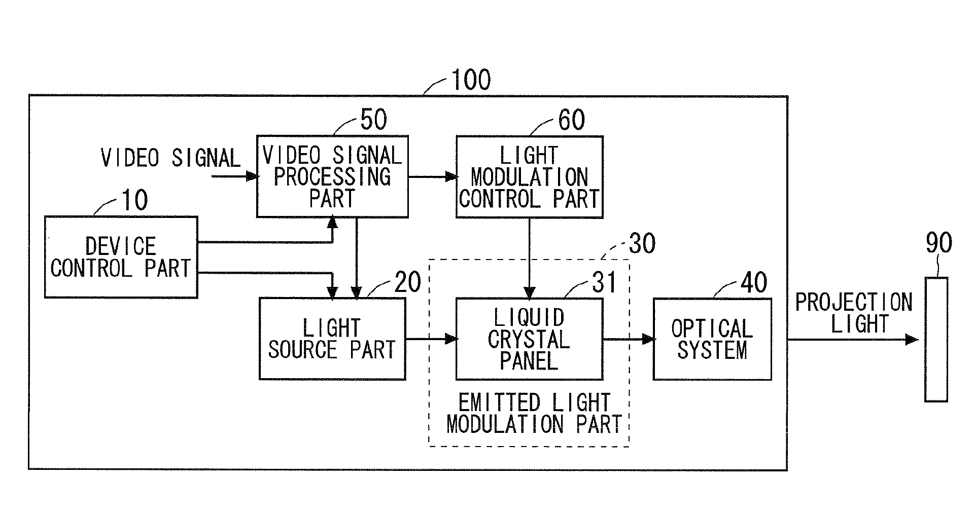
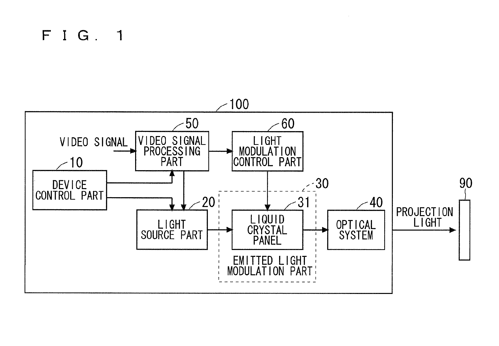
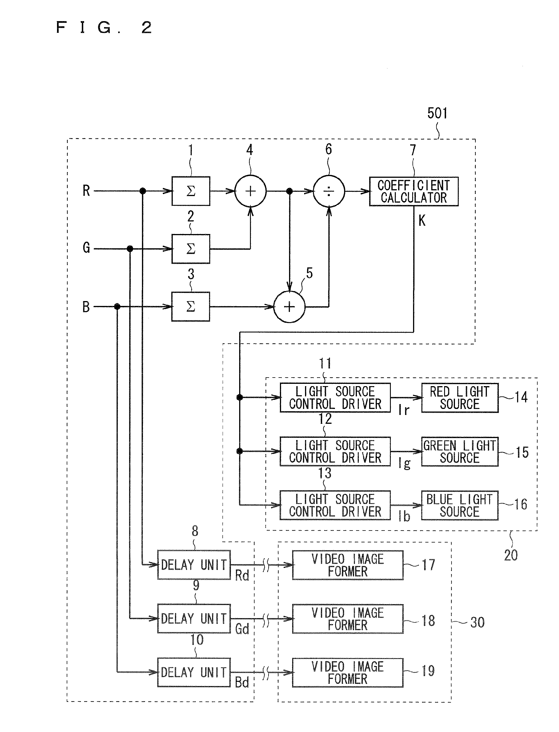
[0043]FIG. 2 is a block diagram showing the configurations of a blue light effect alleviating part 501, a light source 20, and an emitted light modulation part 30 of a projector according to the first preferred embodiment of the present invention. Note that the blue light effect alleviating part 501 is included in the video signal processing part 50 shown in FIG. 1.

[0044]As shown in FIG. 2, the blue light effect alleviating part 501 mainly includes sum calculators 1, 2, and 3, adders 4 and 5, a divider 6, a coefficient calculator 7, and delay units 8, 9, and 10.

[0045]The light source 20 mainly includes a red light source 14, a green light source 15, a blue light source 16, a light source control driver 11 that drives the red light source 14, a light source control driver 12 that drives the green light source 15, and a light source control driver 13 that drives the blue light source 16.

[0046]In a case where a projected video image includes only a high ratio of blue light, the blue li...

second preferred embodiment

[0068]FIG. 3 is a block diagram showing the configurations of a blue light effect alleviating part 502, a light source 20, and an emitted light modulation part 30 of a projector according to a second preferred embodiment of the present invention, where like reference numerals denote similar elements to those of the blue light effect alleviating part 501 shown in FIG. 2, and overlapping description is not given here. The blue light effect alleviating part 502 is included in the video signal processing part 50 shown in FIG. 1.

[0069]As shown in FIG. 3, the blue light effect alleviating part 502 mainly includes the sum calculators 1, 2, and 3, the adders 4 and 5, the divider 6, the coefficient calculator 7, the delay units 8, 9, and 10, and multipliers 20A, 21, and 22.

[0070]In a case where a projected video image includes only a high ratio of blue light, the blue light effect alleviating part 502 generates a blue light effect alleviating signal for controlling the light source 20 to red...

third preferred embodiment

[0091]FIG. 5 is a block diagram showing the configuration of a blue light effect alleviating part 503, a light source 20, and an emitted light modulation part 30 of a projector according to a third preferred embodiment of the present invention, where like reference numerals denote similar elements to those of the blue light effect alleviating part 502 shown in FIG. 3, and overlapping description is not given here. The blue light effect alleviating part 503 is included in the video signal processing part 50 shown in FIG. 1.

[0092]As shown in FIG. 5, the blue light effect alleviating part 503 mainly includes the sum calculators 1, 2, and 3, the adders 4 and 5, the divider 6, the coefficient calculator 7, the delay units 8, 9, and 10, and the multipliers 20A, 21, and 22.

[0093]The blue light effect alleviating part 503 generates a blue light effect alleviating signal for controlling the light source part 20 to reduce the brightness of a projected video image in a case where only a ratio ...


PUM


Abstract

A projector includes a light modulation part modulating light generated by a light source part, a video signal processing part processing a video signal to be input, and a projection optical system projecting the light modulated by the light modulation part onto an external projection target to obtain a projected video image. The video signal processing part includes a blue light effect alleviating part alleviating effects of blue light on retinas. In a case where among a red signal, a green signal, and a blue signal included in a video signal, only a ratio of the blue signal is high, the blue light effect alleviating part generates a blue light effect alleviating signal for controlling the light source part to reduce the brightness of the projected video image as a whole.

Description

BACKGROUND OF THE INVENTION[0001]1. Field of the Invention[0002]The present invention relates to a projector, and more particularly, to a projector capable of protecting retinas from projection light.[0003]2. Description of the Background Art[0004]In a projector, light of three primary colors, i.e., red light, green light, and blue light, are normally used as a light source for achieving color display. A cathode-ray tube (CRT), a halogen lamp, a xenon lamp, a metal halide lamp, an extra-high pressure mercury lamp, and the like have been used as the light source thereof. Recently, along with growing awareness of energy conservation, projectors including light emitting diodes (LEDs) and laser capable of reducing power consumption as a light source have also appeared on the market.[0005]As to the above-mentioned projector, attention should be paid to effects of blue light on retinas. It is known that in a case where retinas are exposed to the light having a wavelength of mainly 400 nm ...

Claims


Application Information

Patent Timeline
Patent Type & Authority Applications(United States)
IPC IPC(8): G09G1/00
CPCG09G1/002H04N9/3155H04N9/3158H04N9/3182G03B21/2053G03B21/2086H04N9/643H04N9/68H04N9/7933H04N9/3194G09G3/3413
Inventor ASAKAWA, KATSUMI
Owner MITSUBISHI ELECTRIC CORP
Learn More