
Water content measuring apparatus

Inactive Publication Date: 2013-10-31
HAMMERTECH
View PDF4 Cites 27 Cited by
  • Summary
  • Abstract
  • Description
  • Claims
  • Application Information

AI Technical Summary

Benefits of technology

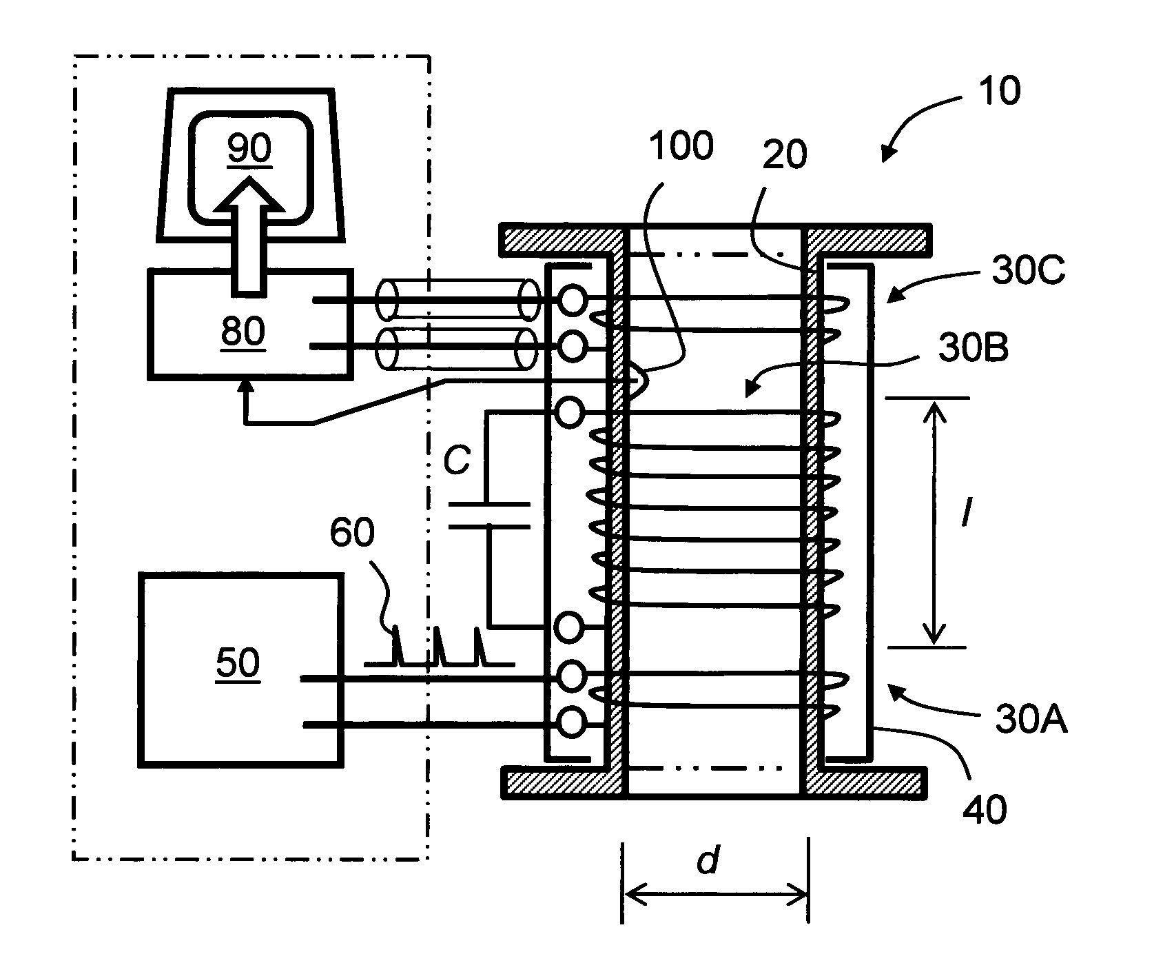
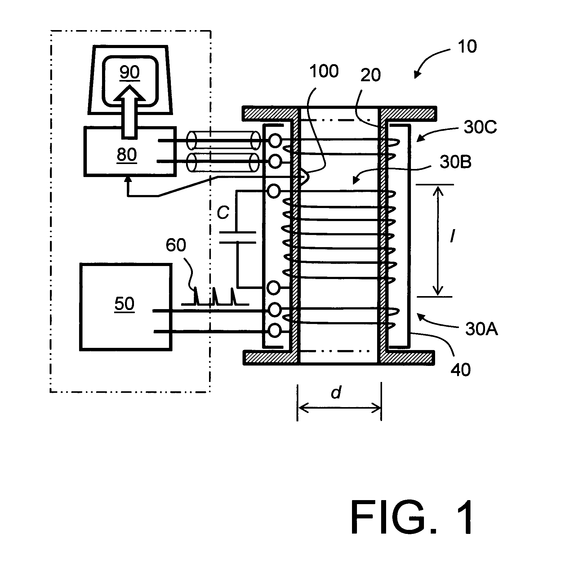
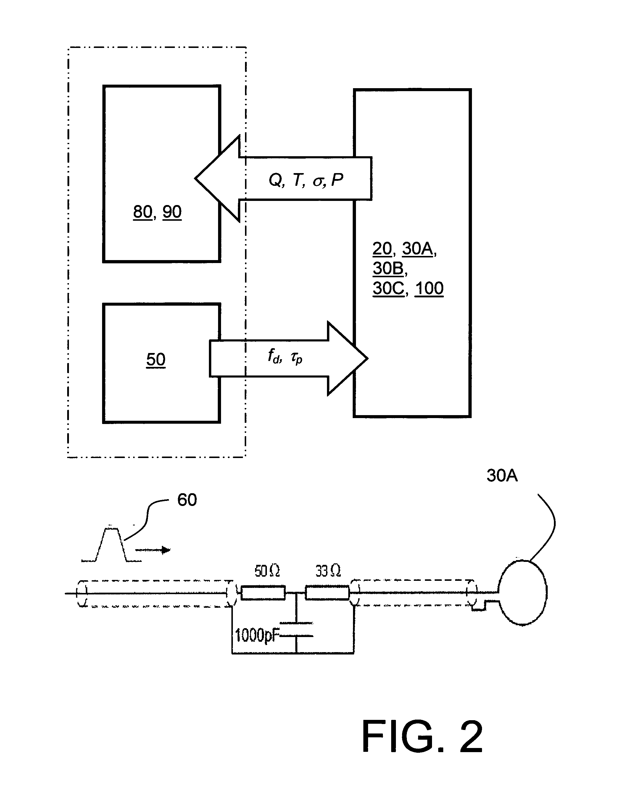
The invention is about an apparatus that can measure small amounts of water in a tube to detect potential hydrate formation. The apparatus includes a coil arrangement with three coils: an excitation coil, a resonance coil, and a pickup coil. The coils are made of insulated wires or metallic tape, and are silver plated to reduce their resistance. The tube is made of materials like polycarbonate or acrylic polymers, which are resistant to high temperatures and have good mechanical and chemical properties. The apparatus measures the water content in the tube by measuring the resonance characteristic of the coil arrangement.

Problems solved by technology

The pair of coils is susceptible, for example, to being used to monitor fluids extracted from a production borehole when water, oil, sand particles and scum can potentially simultaneously be present in the fluids.
A contemporary issue is that geological oil reserves are becoming rapidly depleted, requiring oil companies to revert to difficult and expensive off-shore drilling and production to meet World demand for oil; the World demand is presently estimated to be 85 million barrels of oil equivalent per day.
A contemporary problem encountered with gas production is spontaneous formation of hydrate deposits which can block tubes completely and therefore threaten gas production with associated financial loss.
The blockages grow initially on inside walls of tubes, and eventually obstruct a central region of the tubes.
Moreover, the blockages are also often rather difficult to remove when formed, sometimes requiring costly “pigging” or heat treatment to be performed.
However, using additives is expensive and can also potentially cause a degree of contamination in gas flows.
Contemporary sensors and associated measuring instruments for sensing hydrate formation in tubes are complex and costly, thereby limiting locations whereat they can be installed in gas production systems.
Consequently, many locations along gas tubes and pipes which could beneficially be provided with measuring instruments capable of detecting potential formation of hydrate deposits are hindered from being accordingly equipped on account of cost of conventional hydrate measuring instruments.

Method used


Image

  • Water content measuring apparatus
  • Water content measuring apparatus
  • Water content measuring apparatus

Examples


Embodiment Construction

[0035]It is well known that cylindrical conductor coils exhibit electrical resonances on account of inductance and distributed capacitances associated with such conductor coils; such “distributed capacitances” contributed to resonant circuit tuning capacitors pursuant to the present invention. The distributed capacitances correspond to inter-winding capacitances. Moreover, the inductance arises on account of magnetic flux developed by the coils. However, as aforementioned, it is conventionally perceived that such coils are only capable of providing multiphase mixture measurement to an error deviation of a few percent. For measuring conditions of potential hydrate formation, it is necessary to measure water content to concentrations of a few parts per million (p.p.m.). Thus, it has been conventional practice to regard an electrical resonance coil as being quite unsuitable for use in making precision hydrate-related measurements.

[0036]Experimental studies associated with devising the ...


PUM


Abstract

A water content measuring apparatus, for measuring water content present in a fluid flow through a tube, includes a pulse generator for generating in operation a temporal series of excitation pulses, a coil arrangement disposed around the tube adapted to be excited into resonance by the series of excitation pulses and interact with the fluid flow through the tube, and a signal processor adapted to receive resonance signals from the coil arrangement for determining a water content present within the tube. The coil arrangement includes a resonance coil having a length-to-diameter ratio which is at least 3:1, and wherein the resonance coil includes at least 10 turns.

Description

FIELD OF THE INVENTION[0001]The present invention relates to water content measuring apparatus, for example to a water content measuring apparatus for monitoring water content in fluid flows, for example for monitoring water content in fluid flows wherein conditions for hydrate deposit formation can potentially arise. Moreover, the present invention relates to methods of measuring water content in fluid flows, for example to methods of measuring water content in fluid flows in conditions wherein hydrate deposit formation can potentially arise. Furthermore, the present invention concerns software products recorded on machine-readable media, wherein the software products are executable on computing hardware for implementing aforesaid methods.BACKGROUND OF THE INVENTION[0002]It is known to employ a pair of coils of wire exhibiting mutually different responses and excited with alternating signals for determining phase characteristics of a fluid region intersected by magnetic and electri...

Claims


Application Information

Patent Timeline
IPC IPC(8): G01R27/26
CPCG01R27/2611G01N27/023
Inventor HAMMER, ERLING
Owner HAMMERTECH
Learn More