
Electrostatic chuck with advanced RF and temperature uniformity

Active Publication Date: 2013-10-24
APPLIED MATERIALS INC
View PDF5 Cites 162 Cited by
  • Summary
  • Abstract
  • Description
  • Claims
  • Application Information

AI Technical Summary

Benefits of technology

This patent text is about a need for better control and distribution of temperature and RF in plasma processing to handle larger workpiece diameters and high power loads. The technical effect of this invention is to address these challenges with a faster response time and higher power capacity.

Problems solved by technology

Long line lengths in a heat transfer fluid loop, and the large heat transfer fluid volumes associated with such long line lengths are detrimental to temperature control response times. Point-of-use systems are one means to reduce fluid loop lengths / volumes.
However, physical space constraints disadvantageously limit the power loads of such point-of-use systems.

Method used


Image

  • Electrostatic chuck with advanced RF and temperature uniformity
  • Electrostatic chuck with advanced RF and temperature uniformity
  • Electrostatic chuck with advanced RF and temperature uniformity

Examples


Embodiment Construction

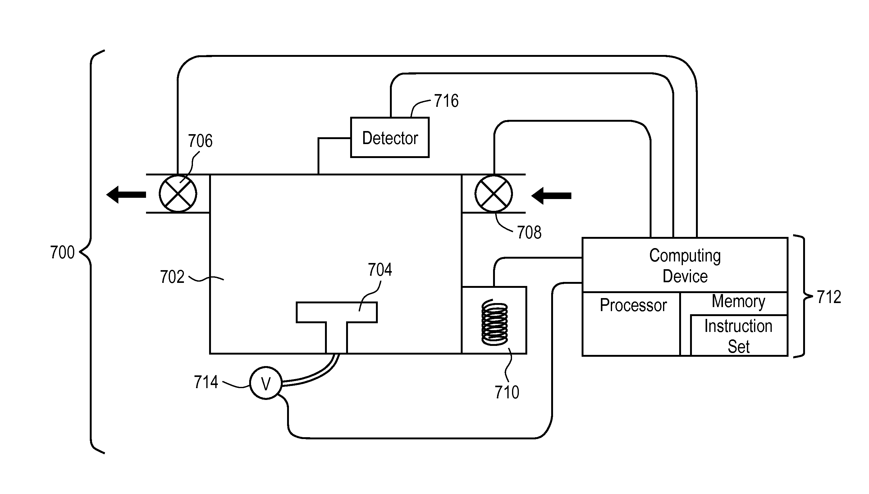
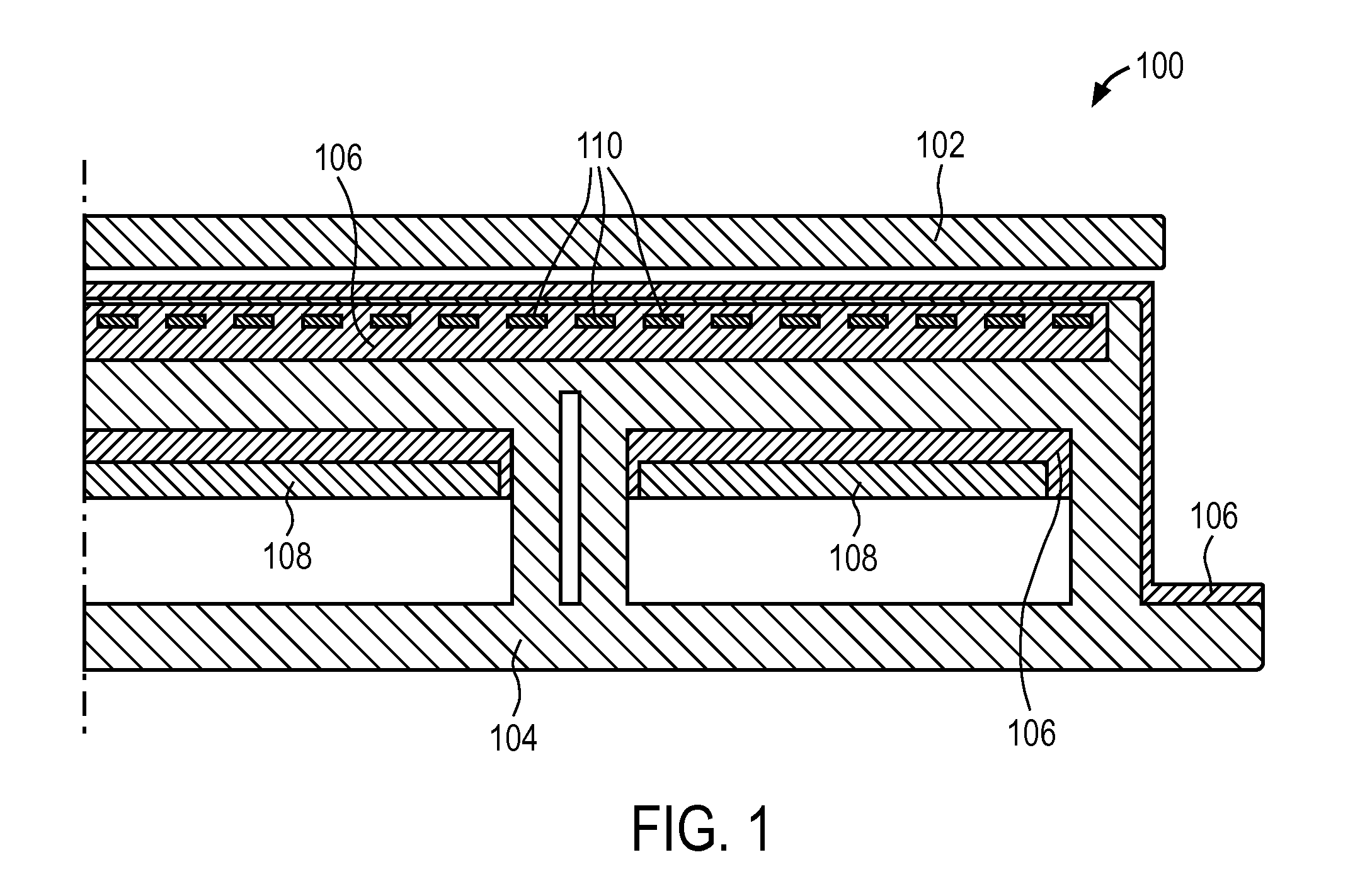
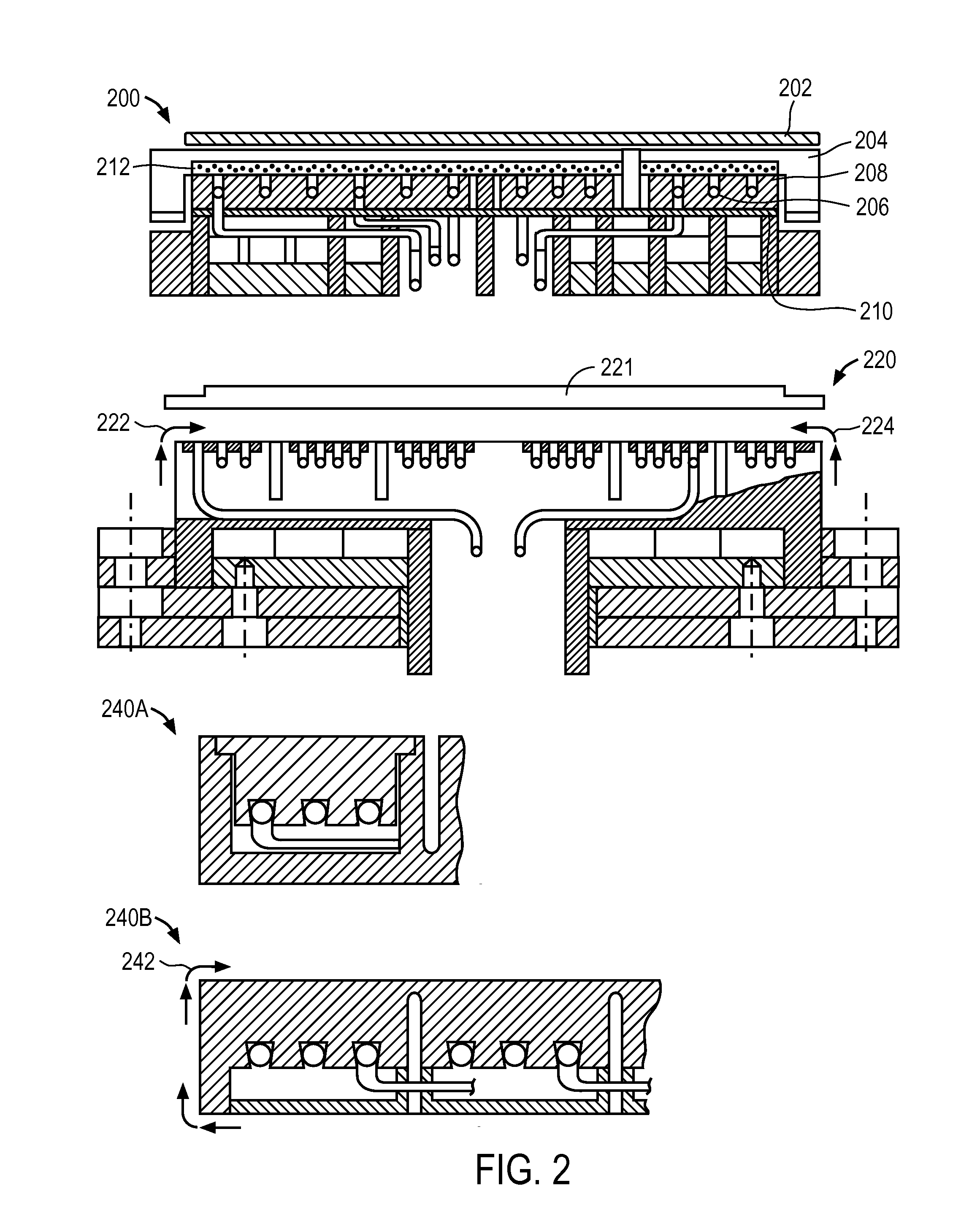
[0017]Electrostatic chucks with advanced RF and temperature uniformity, and methods of fabricating such electrostatic chucks, are described. In the following description, numerous specific details are set forth, such as specific chuck material regimes, in order to provide a thorough understanding of embodiments of the present invention. It will be apparent to one skilled in the art that embodiments of the present invention may be practiced without these specific details. In other instances, well-known aspects, such as etch processing in the presence of a wafer supported by a chuck, are not described in detail in order to not unnecessarily obscure embodiments of the present invention. Furthermore, it is to be understood that the various embodiments shown in the Figures are illustrative representations and are not necessarily drawn to scale.

[0018]One or more embodiments described herein relate to electrostatic chucks with advanced RF and temperature uniformity or systems including ele...


PUM


Abstract

Electrostatic chucks (ESCs) with RF and temperature uniformity are described. For example, an ESC includes a top dielectric layer. An upper metal portion is disposed below the top dielectric layer. A second dielectric layer is disposed above a plurality of pixilated resistive heaters and surrounded in part by the upper metal portion. A third dielectric layer is disposed below the second dielectric layer, with a boundary between the third dielectric layer and the second dielectric layer. A plurality of vias is disposed in the third dielectric layer. A bus power bar distribution layer is disposed below and coupled to the plurality of vias. A fourth dielectric layer is disposed below the bus bar power distribution layer, with a boundary between the fourth dielectric layer and the third dielectric layer. A metal base is disposed below the fourth dielectric layer. The metal base includes a plurality of high power heater elements housed therein.

Description

CROSS-REFERENCE TO RELATED APPLICATIONS[0001]This application claims the benefit of U.S. Provisional Application No. 61 / 637,500, filed Apr. 24, 2012, and U.S. Provisional Application No. 61 / 775,372, filed Mar. 8, 2013, the entire contents of which are hereby incorporated by reference herein.BACKGROUND[0002]1) Field[0003]Embodiments of the present invention pertain to the field of semiconductor processing equipment and, in particular, to electrostatic chucks with advanced RF and temperature uniformity, and methods of fabricating such electrostatic chucks.[0004]2) Description of Related Art[0005]In a plasma processing chamber, such as a plasma etch or plasma deposition chamber, the temperature of a chamber component is often an important parameter to control during a process. For example, a temperature of a substrate holder, commonly called a chuck or pedestal, may be controlled to heat / cool a workpiece to various controlled temperatures during the process recipe (e.g., to control an ...

Claims


Application Information

Patent Timeline
IPC IPC(8): H02N13/00
CPCH02N13/00H01L21/6833Y10S269/903H01L21/67103
Inventor LUBOMIRSKY, DMITRYSUN, JENNIFER Y.MARKOVSKY, MARKMAKHRATCHEV, KONSTANTINBUCHBERGER, JR., DOUGLAS A.BANNA, SAMER
Owner APPLIED MATERIALS INC
Learn More