
Illumination systems for reflective displays

a technology of illumination system and reflective display, which is applied in the direction of fixed installation, lighting and heating apparatus, instruments, etc., to achieve the effect of high contrast ratio, dark display surface, and high contrast ratio

Active Publication Date: 2013-10-24
E INK CORPORATION
View PDF10 Cites 51 Cited by
  • Summary
  • Abstract
  • Description
  • Claims
  • Application Information

AI Technical Summary

Benefits of technology

The present invention provides a display device that combines a reflective display and a projection display on a common frame. This allows for the creation of a display that can show both images simultaneously, with the reflection of the second image on the reflective display. The invention also provides a method for directing different image components to different display surfaces, allowing for more flexibility in the display. Additionally, the invention provides an electrophoretic display with improved image quality and a method for controlling the movement of the display particles. The technical effects of the invention include improved display flexibility, reduced power demands, and improved image quality.

Problems solved by technology

Nevertheless, problems with the long-term image quality of these displays have prevented their widespread usage.
For example, particles that make up electrophoretic displays tend to settle, resulting in inadequate service-life for these displays.
Such gas-based electrophoretic media appear to be susceptible to the same types of problems due to particle settling as liquid-based electrophoretic media, when the media are used in an orientation which permits such settling, for example in a sign where the medium is disposed in a vertical plane.
Indeed, particle settling appears to be a more serious problem in gas-based electrophoretic media than in liquid-based ones, since the lower viscosity of gaseous suspending fluids as compared with liquid ones allows more rapid settling of the electrophoretic particles.
All emissive displays have the disadvantage that their contrast and colorfulness both depend upon the intensity of ambient light.
In very bright environments, such as sunlight, the emitted light may be overwhelmed and the displayed information difficult to see.
However, reflective displays are obviously difficult to see in dim light.
A further difficulty arises with reflective displays intended to render colored images.
Although a color image is thus provided to the viewer, the color filters necessarily reduce the amount of light reflected from the display in the white state, and the necessary sharing of the available display surface area between the different color primaries limits colorfulness and color gamut.
Conversely, the legibility of information on a reflective display suffers under very low lighting conditions so that the illumination of the display must be increased accordingly to counter the loss of contrast and colorfulness.
However, no equivalent solution is currently known to increase the contrast and colorfulness of reflective displays.
The main drawback to this system is the need to maintain exact registration between the active projection screen and the projector.
Without rigid mechanical coupling of projector and screen the required exact alignment and registration are very difficult to achieve and maintain, and the solution described in the '486 patent, namely electronic coupling between projector and screen via ‘reflectance processor’ and ‘display controller’, is expensive.
The system described in the '486 patent is a large-size emissive (projection) display, and the patent does not disclose any device in which color projection means image and means for rendering a reflective image are incorporated into the same device, such that both images can be rendered in registration with each other.
Both incandescent bulbs and LED's (and indeed, all other emissive light sources) require a continuous source of power, typically mains alternating current power, so that any disruption of the power supply due to equipment failure, weather conditions or traffic accidents will result in failure of the traffic lights, traffic hazards and major disruption of traffic flow.
Conventional traffic signals have other disadvantages, including:(a) false signals can occur as a result of sun light and solar glare; conventional traffic lights must overcome ambient light conditions, including specular reflections from various surfaces of the sign, which can make it difficult to discriminate between off and on states of a particular sign, to be noticeable and effective; even the common use of light baffles and high powered LED or incandescent lamps in the range of 25-100 W do not entirely overcome such problems;(b) traffic lights are located outdoors and hence are subject to harsh mechanical and environmental conditions; they must withstand mechanical damage and remain operational despite vandalism, mechanical shock and impact, extreme temperatures, and exposure to ultraviolet radiation;(c) total cost of ownership, particularly operating costs, is very important factor in traffic light usage; in New York city alone there are 11,871 traffic lights, and substantial effort is devoted to reducing power usage, including converting incandescent signals to LED's;(d) strict weight restrictions exist for streetlights to prevent overloading of signage support structures, so industrial design and weight allocations must be carefully managed for signage; and(e) the need (in some cases) for increasing traffic signal size may compromise performance in terms of power consumption, weight, and cost.
Similar problems are encountered when the “traffic control device” is an indicator on an automobile or other vehicle.
Even relatively high powered bulbs do not guarantee sufficient visibility.
Although such a parabolic reflector does help to concentrate the light from the brake light into a narrow beam, it also concentrates any light incident on the reflective enclosure (for example, from sunlight or light from the headlights of a following vehicle) back through the colored plastic cover, thus creating background reflection that tends to obscure the state of the brake light.
In the worst case, when the sun faces the back of the car, the specular reflection of the parabolic reflective enclosure, the reflection of the glossy paint on the car and the reflection from the rear windscreen combine to significantly lower the visibility of the brake light.

Method used


Image

  • Illumination systems for reflective displays
  • Illumination systems for reflective displays
  • Illumination systems for reflective displays

Examples


Embodiment Construction

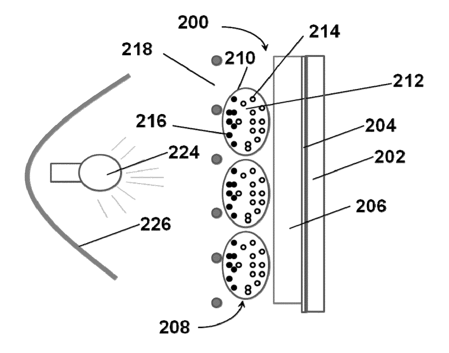
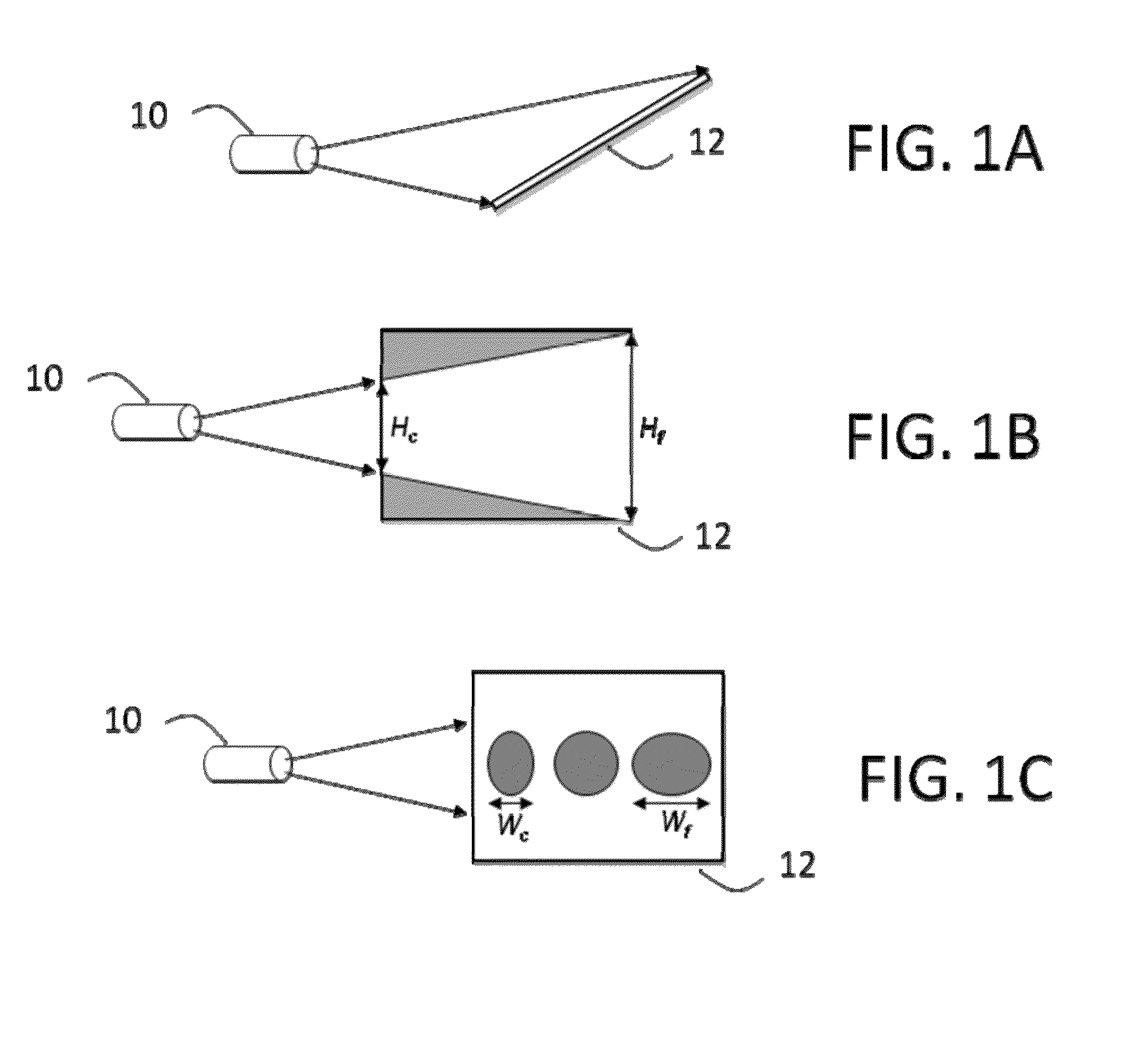
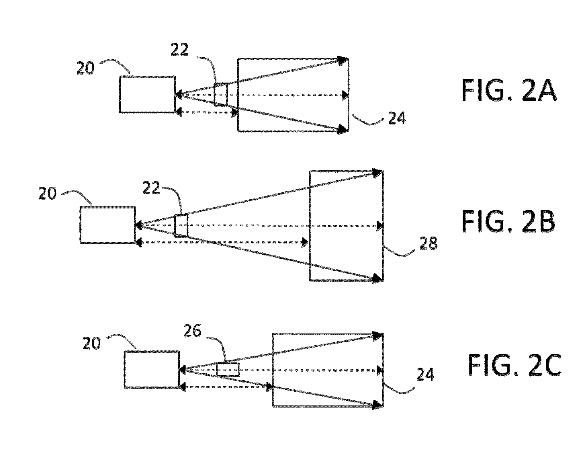
[0070]As indicated above, in one aspect the present invention provides a projection display in which means for projecting a color image and means for rendering a reflective image are incorporated into a single unit such that both images can be superimposed in registration with one another, so that a composite image of improved color quality, visible in a wider range of ambient illumination conditions, can be obtained, compared with that which could be rendered by either the reflective display or the projector alone. In low light, the projected image is easily visible, its contrast being enhanced by the reflective image on to which it is superimposed. In bright light the projected image will fade but the reflective image will be well lit and seen to good advantage. In order to conserve power, it is desirable that the intensity of the projected image be adjusted depending on the ambient illumination (whose intensity can be measured by means well known in the art, such as photodiodes, ...


PUM


Abstract

A display device (30) comprises a reflective display (38) arranged to render a first image viewable through a viewing surface and a projection means (31-37) arranged to render a second image viewable in reflection on the viewing surface, the reflective display (38) and the projection means (31-37) being mounted on a common frame.

Description

REFERENCE TO RELATED APPLICATIONS[0001]This application claims benefit of copending provisional Application Ser. Nos. 61 / 636,070, filed Apr. 20, 2012, and 61 / 654,405, filed Jun. 1, 2012. However, the applicant hereby declares, in accordance with 37 CFR 1.78(a)(6), that this application also contains a claim to a claimed invention that has an effective filing date on or after Mar. 16, 2013.[0002]The entire contents of the aforementioned copending applications, and of all patents, copending applications, and published applications mentioned below are herein incorporated by reference.BACKGROUND OF INVENTION[0003]This invention relates to illumination systems for reflective displays. More specifically, this invention relates to a display and means for projecting patterned light onto at least a part of the display. This invention also relates to a method for directing spatially and spectrally modulated illumination on to a reflective display to improve contrast and colorfulness under amb...

Claims


Application Information

Patent Timeline
IPC IPC(8): F21S8/10G03B21/14G02F1/167G02F1/1677
CPCF21S48/23G03B21/14G02F1/167F21S43/26F21V14/003G03B21/608G03B21/10G03B21/62F21S41/645G02F1/1677F21S43/30F21S43/2605
Inventor HERTEL, DIRKPAOLINI, JR., RICHARD J.PALETSKY, BENJAMIN HARRISTELFER, STEPHEN J.SAINIS, SUNIL KRISHNAMANCINI, GIOVANNISHEA, COLLEENBISS, DAVID PAULFANTONE, STEPHEN DENNIS
Owner E INK CORPORATION
Learn More