Scroll structure of centrifugal compressor

Active Publication Date: 2013-10-17
MITSUBISHI HEAVY IND LTD
View PDF12 Cites 4 Cited by
  • Summary
  • Abstract
  • Description
  • Claims
  • Application Information

AI Technical Summary

Benefits of technology

The present invention aims to solve the problem of low efficiency in centrifugal compressors by forming portions where the air flow is accelerated and decelerated in the scroll to allow adequate static pressure recovery. This results in a high efficiency and high pressure as the centrifugal pressure. By gradually increasing or decreasing the radius in the scroll, a boundary layer is formed between the scroll wall surface and the fluid, which reduces the flow resistance and facilitates static pressure recovery. Additionally, smoothening the change of the boundary layer by forming arc relief portions at specific ranges and suppressing turbulence, the compressor performance is improved without losing the static pressure. Overall, the invention achieves high efficiency and high pressure as the centrifugal compressor by optimizing air flow dynamics.

Problems solved by technology

In the conventional art as shown in FIG. 7, the deceleration of the air flow is carried out by the diffuser portion 13, and the air flow is not decelerated in the scroll, which results in a loss in the scroll 12 so that it has not been possible to obtain high efficiency and high pressure as the centrifugal compressor.
On the other hand, when the air flow is decelerated in the scroll 12, the thickness of a boundary layer generated between the scroll wall and the fluid is increased so that the static pressure cannot be adequately recovered.

Method used


Image

  • Scroll structure of centrifugal compressor
  • Scroll structure of centrifugal compressor
  • Scroll structure of centrifugal compressor

Examples


first embodiment

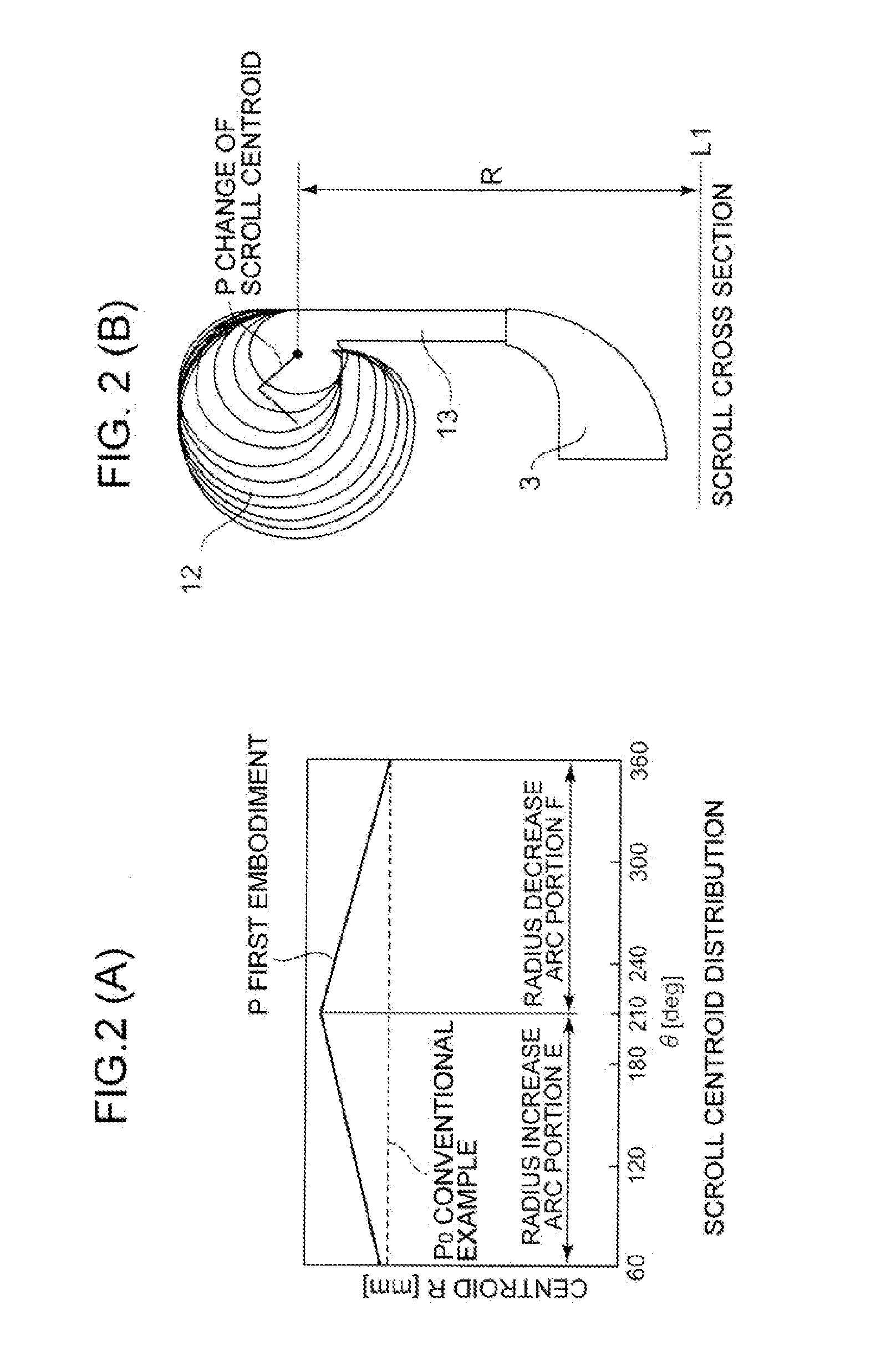
[0040]As shown in FIG. 5, in a scroll of the present invention, there are provided, as a flow path of a fluid, a diffuser portion 13 which is formed on the outer peripheral side of a compressor impeller 3 in a substantially toroidal shape and recovers a static pressure by decelerating an air flow discharged from the compressor impeller 3, a scroll 12 which is formed on the outer peripheral side of the diffuser portion 13 such that the cross-sectional area thereof is spirally increased in a circumferential direction, and decelerates and pressurizes the air flow, and an exit pipe (not shown).

[0041]When the compressor impeller 3 rotates, a centrifugal blade 32 compresses a fluid such as gas or air introduced from an air passage 15. The flow of the fluid (air flow) formed in this manner passes through the diffuser portion 13 and the scroll 12 from the outer peripheral end of the compressor impeller 3 to be sent to the outside from the exit pipe.

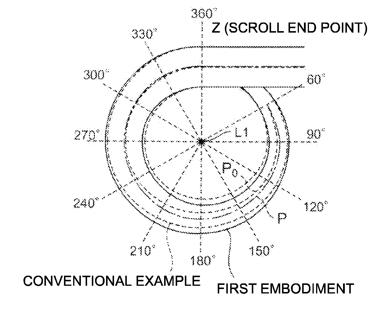
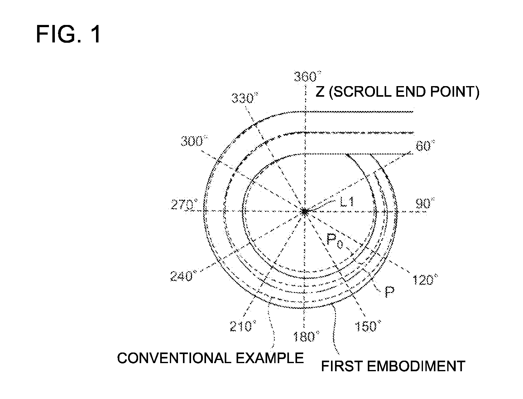
[0042]On the basis of FIG. 1 and FIGS. 2(A...

second embodiment

[0066]On the basis of FIG. 3 and FIGS. 4(A) and 4(B), a description is given of a scroll structure of a centrifugal compressor according to a second embodiment of the present invention.

[0067]Note that the description of the same components as those in the first embodiment is omitted by retaining the same reference numerals.

[0068]FIG. 3 is a view of the scroll 12 as viewed in plan view in which the solid line indicates the shape of the second embodiment and the broken line indicates the shape of the conventional example.

[0069]In the scroll structure, the radial cross section of the scroll 12 is substantially circular, and the area of the cross section is gradually increased spirally from the position at 60° to 260° in the clockwise direction with the scroll endpoint Z used as the 0 reference to form the radius increase arc portion E of the radius of the scroll centroid P.

[0070]In addition, the distance from the rotational axis center L1 of the scroll 12 to the scroll centroid P as th...


PUM


Abstract

In a scroll structure of a centrifugal compressor, there are provided a radius increase arc portion E in which a radius from the center of a scroll 12 to a scroll centroid P of the cross section of the scroll 12 is gradually increased in any range in a circumferential direction from the start of winding of the scroll, and a radius decrease arc portion F in which the radius is gradually decreased toward a scroll end point Z.

Description

TECHNICAL FIELD[0001]The present invention relates to a centrifugal compressor having a scroll portion structure which constitutes a flow path spirally formed in an outer peripheral portion of a compressor impeller by rotation of the compressor impeller, and relates to a scroll structure which recovers a static pressure in the scroll portion.BACKGRPUND ART[0002]A centrifugal compressor is required to have high pressure and high efficiency in a wide operation range.[0003]FIG. 5 is an enlarged cross-sectional view of a principal portion of the upper half of the centrifugal compressor above the rotational axis center of a compressor impeller.[0004]A compressor 1 of the centrifugal compressor includes a turbine rotor 2 in which a compressor impeller 3 mainly comprised of a rotary hub 31 and a large number of centrifugal blades 32 attached to the outer peripheral surface of the hub 31 is coupled to a rotation drive source using a shaft, and a compressor housing 11 which accommodates the ...

Claims


Application Information

Patent Timeline
IPC IPC(8): F01D25/24
CPCF01D25/24F04D29/441F04D29/681F05D2250/52
Inventor HOSHI, TORUTOMITA, ISAOEBISU, MOTOKISUZUKI, HIROSHISHIRAISHI, TAKASHI
Owner MITSUBISHI HEAVY IND LTD
Why Eureka
Try Eureka