
Joint Member and Method for Producing the Same, and Method for Producing Metal Composite Molded Product

a joint member and metal composite technology, applied in the direction of adhesive processes, manufacturing tools, mechanical equipment, etc., can solve the problems of increasing the weight of the obtained joint member, the strength of the obtained joint is not always sufficient with only the adhesive, and the joint to the metal by welding is difficult, etc., to achieve the effect of preventing the electrolytic corrosion caused by carbon fiber simultaneously, short time period, and less number of steps

Inactive Publication Date: 2013-10-17
TEIJIN LTD
View PDF7 Cites 31 Cited by
  • Summary
  • Abstract
  • Description
  • Claims
  • Application Information

AI Technical Summary

Benefits of technology

The present invention provides a method for joining a carbon fiber composite material containing a resin as a matrix and a metal by a simultaneous joint and molding process. This method prevents electrolytic corrosion caused by carbon fiber and achieves a strong and stable joint between the two materials. The joint member can be obtained in a short period of time with fewer steps and can be used in various applications.

Problems solved by technology

As a result, there is a concern in great increase in weight of the member obtained, and additionally, there is a defect that its strength is not always sufficient with only the adhesive.
Furthermore, because much time is required until the adhesive develops generally practical strength, an aging step must be taken into consideration.
However, there are many cases that the joint to a metal by welding is difficult even in the thermoplastic carbon fiber composite material.
Thus, the resin is not always homogeneously present on the surface of the material, and in some cases, a “deficient” portion of a resin is present.
Therefore, there was a concern that sufficient joint strength is not developed and joint strength shows great variations.
Furthermore, the carbon fiber causes a so-called electrolytic corrosion to a metal.
Therefore, when the carbon fiber has been brought into contact with a metal in a portion where the resin has been deficient, the contact has caused the corrosion of a metal.
Furthermore, in the thermoplastic carbon fiber composite material, because carbon fibers are contained in the composite material, the presence of unevenness on the surface of the composite material is not avoided.
Therefore, it was difficult in conventional methods to strongly join the thermoplastic carbon fiber composite material to the surface of a metal.Patent Document 1: JP-A-2003-103563Patent Document 2: JP-B-5-51671Patent Document 3: WO2009 / 157445 pamphletPatent Document 4: JP-A-2011-235570Patent Document 5: JP-A-2006-297927

Method used

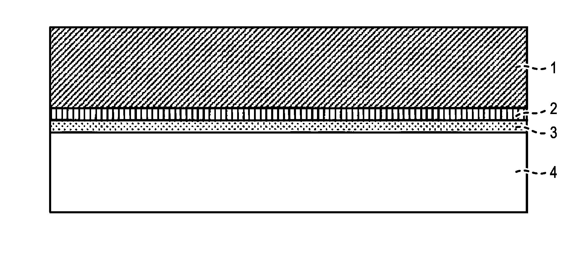
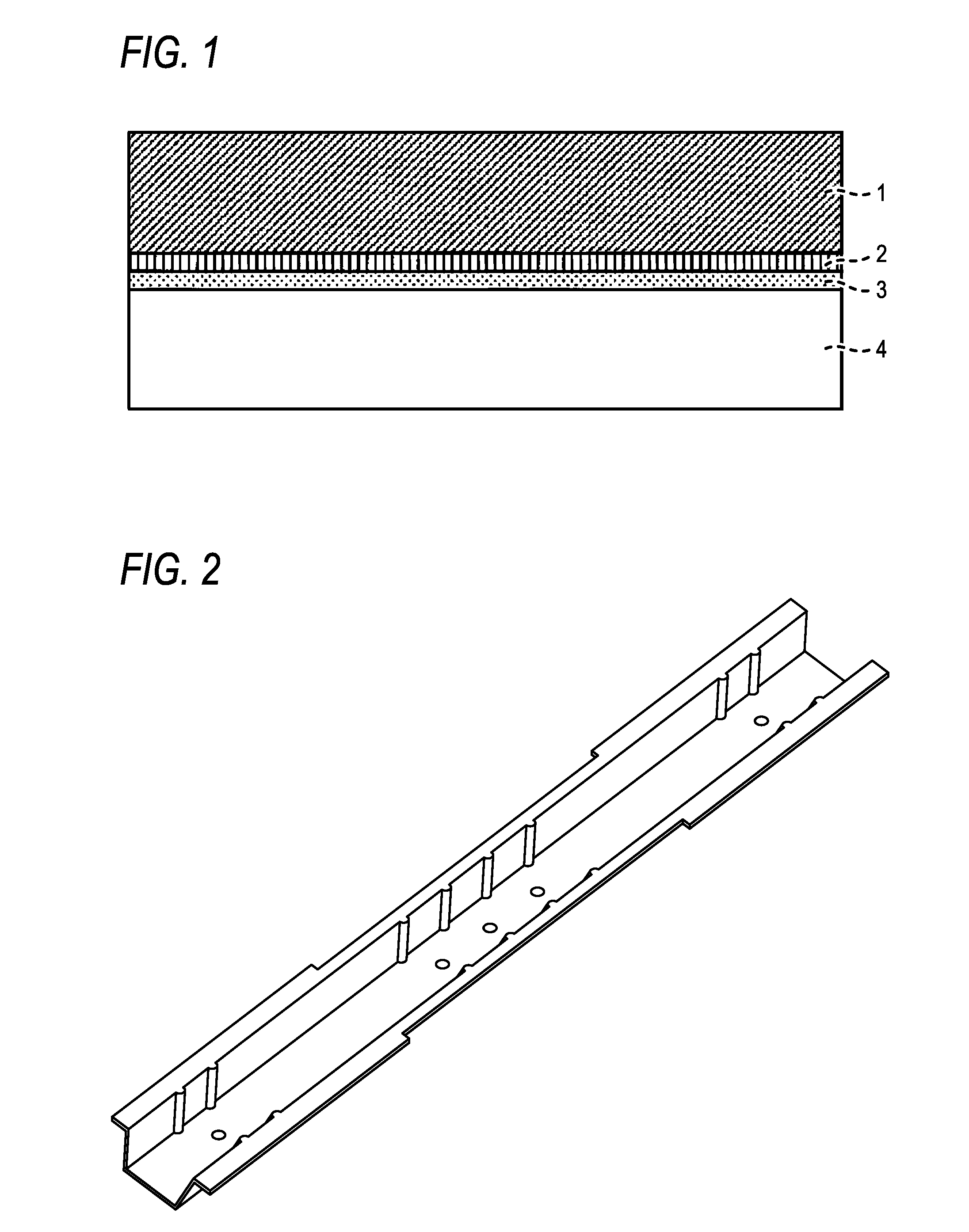
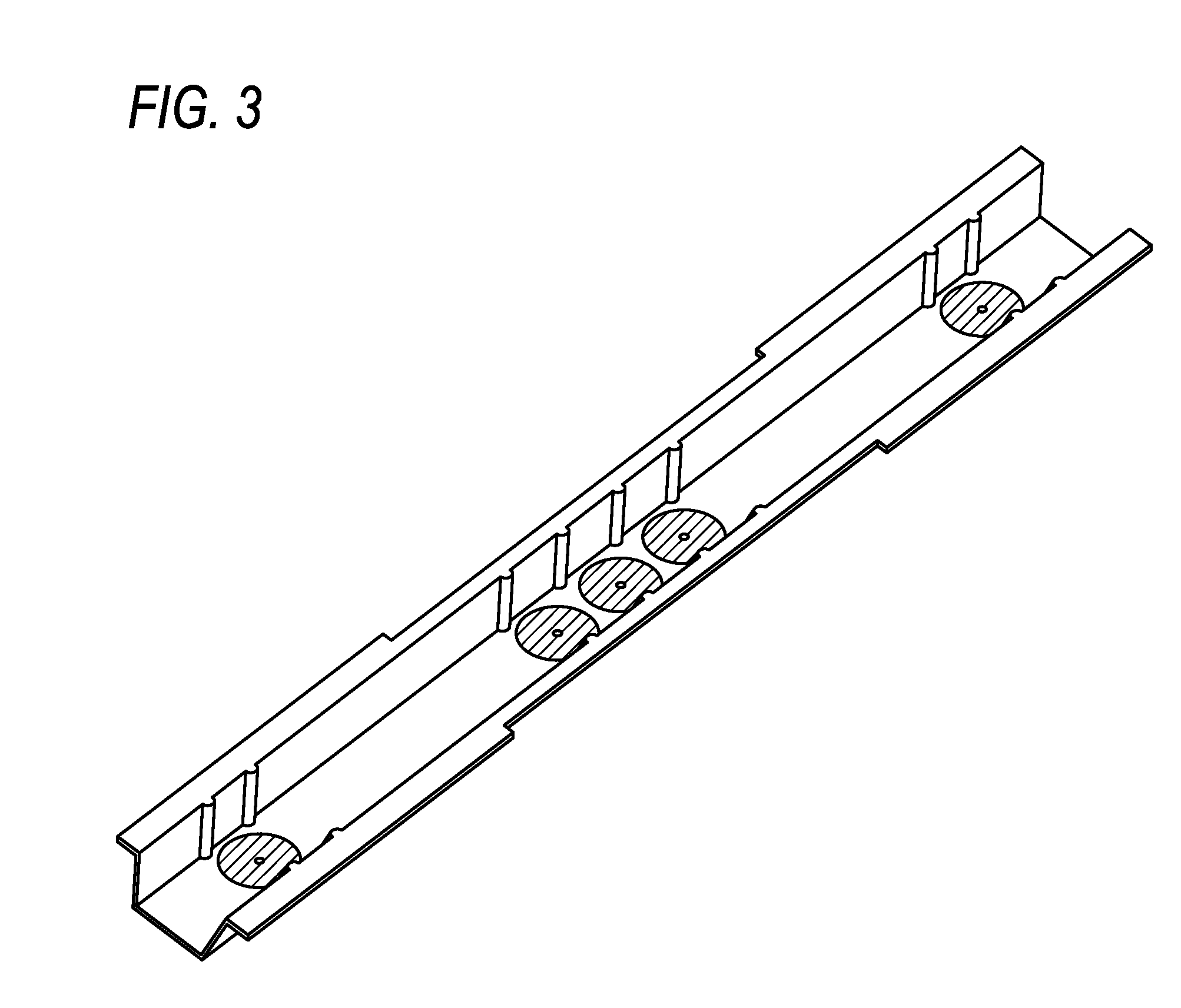

Image

  • Joint Member and Method for Producing the Same, and Method for Producing Metal Composite Molded Product
  • Joint Member and Method for Producing the Same, and Method for Producing Metal Composite Molded Product
  • Joint Member and Method for Producing the Same, and Method for Producing Metal Composite Molded Product

Examples


reference example 1

Production of Carbon Fiber Composite Material of Continuous Fiber 0° and 90° Alternate Stacking Materials

[0079]Strands of carbon fibers (“TENAX”™ STS40-24KS (fiber diameter: 7 μm, tensile strength: 4,000 MPa), manufactured by Toho Tenax Co., Ltd.) and nylon 6 films (“EMBLEM”™ ON, 25 μm thick, manufactured by Unitika Ltd.) were sequentially stacked to stack 64 layers (carbon fiber: 64 layers, nylon: 65 layers) such that layers having a fiber direction of 0° and layers having a fiber direction of 90° were arranged alternately, and the resulting assembly was compressed under heating at 260° C. under a pressure of 2 MPa for 20 minutes. Thus, a carbon fiber composite material having 0° and 90° alternate fibers, symmetric stacking, carbon fiber volume content: 47% (content of carbon fibers in mass basis: 57%) and a thickness of 2 mm was prepared.

reference example 2a

Production of Flat Plate Carbon Fiber Composite Material (A)

[0080]Carbon fibers (“TENAX”™ STS40, average fiber diameter: 7 μm, manufactured by Toho Tenax Co., Ltd.) cut into an average fiber length of 16 mm were randomly arranged such that an average density is 540 g / m2, and were sandwiched among 10 cloths of KE 435-POG (nylon 6), manufactured by Unitika Ltd. The resulting assembly was pressed at 260° C. under 2.5 MPa to prepare a flat plate carbon fiber composite material having 1400 mm×700 mm, a carbon fiber volume content of 35% (content of carbon fibers on the basis of mass: 45%) and a thickness of 2 mm.

reference example 2b

Production of Flat Plate Carbon Fiber Composite Material (B)

[0081]Carbon fibers (“TENAX”™ STS40, average fiber diameter: 7 μm, manufactured by Toho Tenax Co., Ltd.) were cut into an average fiber length of 20 mm and were formed into a carbon fiber sheet in a random arrangement state such that an average density is 540 g / m2. The carbon fiber sheet were sandwiched among cloths of KE 435-POG (nylon 6), manufactured by Unitika Ltd. so as to form an assembly by repeatedly stacking of carbon fiber sheet / nylon 6 cloth. The resulting assembly was pressed at a temperature of 260° C. under a pressure of 2.5 MPa to prepare a flat plate carbon fiber composite material (B) having a carbon fiber volume content of 35% (content of carbon fibers on the basis of mass: 45%) and a thickness of 2 mm.


PUM

PropertyMeasurementUnit
Percent by massaaaaaaaaaa
Thicknessaaaaaaaaaa
Thicknessaaaaaaaaaa

Abstract

A method for producing a joint member between a carbon fiber composite material containing a thermoplastic resin as a matrix and a metal, includes: forming a layer containing a triazine thiol derivative on a surface of the metal; providing a thermoplastic resin layer between the layer containing a triazine thiol derivative and the carbon fiber composite material; and melting the thermoplastic resin layer to join the metal to the carbon fiber composite material.

Description

[0001]This application is a continuation-in-part of International Application No. PCT / JP2011 / 077886 filed on Nov. 25, 2011, which claims priority under 35 U.S.C. §119 from Japanese Patent Application No. 2010-266544 filed on Nov. 30, 2010. This application also claims priority under 35 U.S.C. §119 from Japanese Patent Application Nos. 2012-122121 and 2012-122123, both filed on May 29, 2012. The entire disclosures of the above-mentioned applications are incorporated herein by reference.BACKGROUND[0002]1. Technical Field[0003]The present invention relates to a joint member between a carbon fiber composite material and a metal, a method for producing the same and a method for producing a metal composite molded product.[0004]2. Background Art[0005]A carbon fiber composite material has high specific strength and specific rigidity and is valued as an extremely excellent material. However, in joining a conventional carbon fiber composite material using a thermosetting resin as a matrix to ...

Claims


Application Information

Patent Timeline
IPC IPC(8): C09J5/06
CPCC09J5/06C09J5/02C09J2400/163C09J2400/166B32B7/12B29C65/08B29C65/16B29C65/44B29C65/46B29C65/4815B29C65/8215B29C66/026B29C66/1122B29C66/472B29C66/524B29C66/5326B29C66/61B29C66/71B29C66/7212B29C66/7392B29C66/742B29C66/7422B29C66/74283B29C66/919B29C66/929B29C66/949B29C66/91411B29C66/91921B29C66/91933B29C66/8322B29C66/72143Y10T403/477C09J2301/416B29K2307/04B29K2023/12B29K2077/00B29K2067/00B29K2069/00B29K2081/04B29K2023/10B29K2067/006B29K2067/003B29K2023/06
Inventor TAKEUCHI, MASAKIKANEKO, TORUHIRATA, MASUMIKATO, TAKUMISANO, HIROKI
Owner TEIJIN LTD
Learn More