
System and method for interrogation of target material in situ

Active Publication Date: 2013-10-17
CHEVROU USA INC
View PDF5 Cites 13 Cited by
  • Summary
  • Abstract
  • Description
  • Claims
  • Application Information

AI Technical Summary

Benefits of technology

The device described in this patent combines active hyperspectral imaging with lidar measurements and integrates a materials database to allow for real-time adjustment of parameters during acquisition. It can pre-filter out unwanted target areas and maximize spectral and spatial sampling of areas of high interest, reducing post-processing time and maximizing resolution. The device can also minimize spatial distortion and errors encountered by mis-registration of image-to-spatial model. Additionally, the relatively short travel distance of the electromagnetic radiation from the source to detector in ground-based / terrestrial scanning lidar allows investigation of frequency relationships attenuated by traditional, passive, hyperspectral imaging techniques that rely on sunlight traveling through the Earth's atmosphere.

Problems solved by technology

Although a single frequency laser intensity value can offer some information about a target material's composition, identifying the chemical composition of the target material, such as specific mineralogy, cannot be accomplished by using a single frequency lidar instrument.
Matching of separately obtained lidar information with hyperspectral data can require costly post-processing to perform resolution matching and illumination matching.
Spectral image analysis of passively collected data also requires considerable post-processing to extract meaningful results.
Commercially available instruments cannot be dynamically modified during acquisition to collect maximum resolution of a target material based on real-time feedback from the instrument during acquisition.
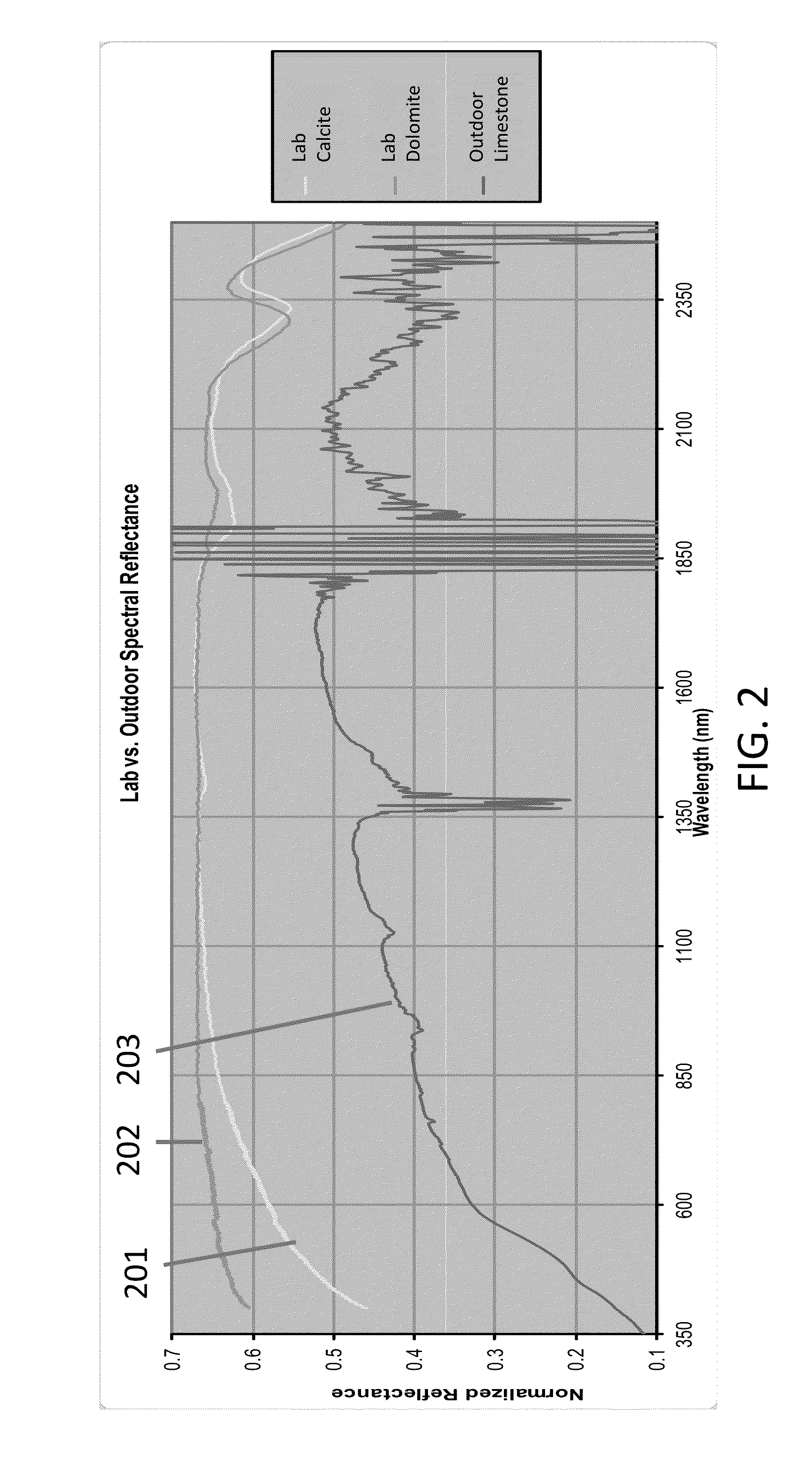
Further, conventional spectral imaging techniques utilizing natural electromagnetic radiation are characterized by incomplete spectral coverage in the reflected infrared spectral region due to absorption of frequencies, e.g., 1400-1600 nm and 1800-2000 nm, from long transit distance through the atmosphere, e.g., several tens of kilometers.

Method used


Image

  • System and method for interrogation of target material in situ
  • System and method for interrogation of target material in situ
  • System and method for interrogation of target material in situ

Examples


Embodiment Construction

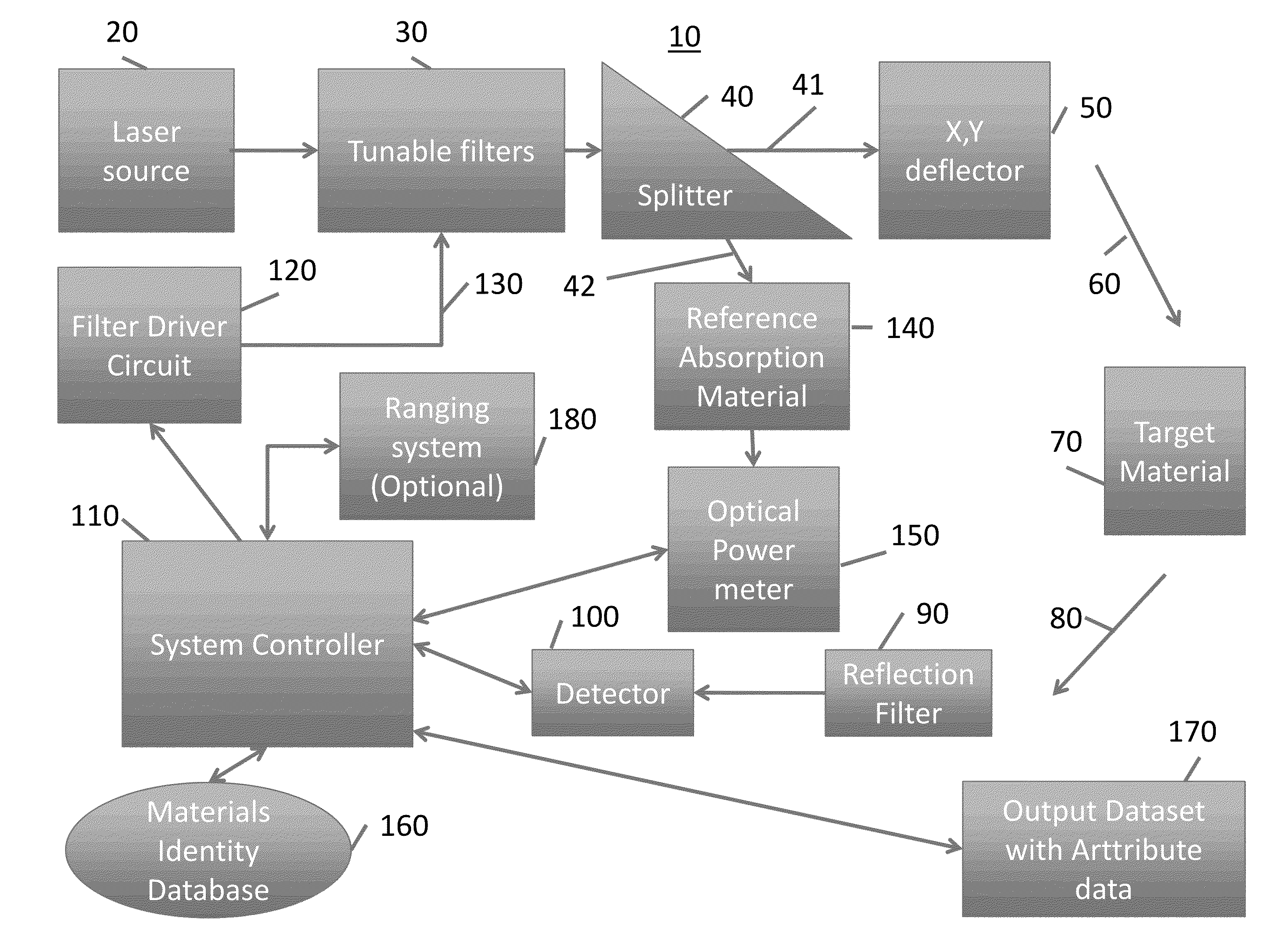
[0017]Embodiments of the present invention for in situ interrogation of target materials are now described with reference to the appended drawings. The invention can be practiced as any one of or combination of hardware and software, including but not limited to a system (including a computer processor), a method (including a computer implemented method), an apparatus, an arrangement, a computer readable medium, a computer program product, a graphical user interface, a web portal, or a data structure tangibly fixed in a computer readable memory. An article of manufacture for use with a computer processor, such as a CD, pre-recorded disk or computer program storage medium having program code residing therein, also falls within the spirit and scope of the present invention.

[0018]Applications of the present invention include but are not limited to the acquisition of physical shape and chemical composition of target material from a remote location without the need for physical contact o...


PUM


Abstract

A system for remotely sensing a target material in situ include a broad-band laser source, at least one tunable filter coupled to the source laser for generating a swept-frequency signal an optical device for splitting the swept-frequency signal into a first illumination signal and second illumination signal, a first optical path for directing the first illumination signal unto the target material and receiving a reflected signal from the target material, a second optical path for receiving the second illumination signal and generating a spectral reference signal, and a controller coupled to the first optical path and the second optical path for adjusting the frequency and spatial resolution of the laser source based at least in part on a comparison of the spectral reference signal and the reflected signal.

Description

FIELD OF THE INVENTION[0001]The present invention relates generally to a system and method for remotely sensing a target material in situ, and more particularly, a system and method for simultaneously providing ranging and hyperspectral data for the target material.BACKGROUND OF THE INVENTION[0002]Remote sensing of geometric shapes and locations of a target material has proven to be valuable in a number of fields, including for the study of geological formations. Conventional technologies include light detection and ranging (“lidar”), which is generally recognized as an “active” remote sensing technique that uses a single laser frequency to actively illuminate a target and determine range. Although a single frequency laser intensity value can offer some information about a target material's composition, identifying the chemical composition of the target material, such as specific mineralogy, cannot be accomplished by using a single frequency lidar instrument. A more complete spectra...

Claims


Application Information

Patent Timeline
IPC IPC(8): G01N21/27G01N21/55G01S17/89
CPCG01N21/27G01N21/55G01J3/26G01S17/89G01S7/4802G01V8/02G01J3/027G01N21/314
Inventor BELLIAN, JEROME ANTHONYTOLLESON, CHRISTOPHER MICHAEL
Owner CHEVROU USA INC
Learn More