
Electronic device

a technology of electronic devices and housings, applied in the direction of electrical equipment, substation equipment, telephone set construction, etc., can solve the problem that the panel attached to the housing is hardly vibrated, and the consideration is barely mad

Active Publication Date: 2013-10-10
KYOCERA CORP
View PDF7 Cites 3 Cited by
  • Summary
  • Abstract
  • Description
  • Claims
  • Application Information

AI Technical Summary

Benefits of technology

The patent describes an electronic device that generates sound by vibrating a part of a person's body. The device includes a piezoelectric element, a vibration plate with the piezoelectric element fixed to it, and a housing with the vibration plate fixed to it. The device also has an operation key. The vibration plate can also create air-conducted sound, which is generated by vibrating air around the person's body. The technical effect of this invention is a small, portable device that can produce high-quality sound without needing to be placed on a person's ears or at close proximity to their face.

Problems solved by technology

Therefore, consideration is barely made for a case that a panel attached to the housing is vibrated.

Method used


Image

  • Electronic device
  • Electronic device
  • Electronic device

Examples


first embodiment

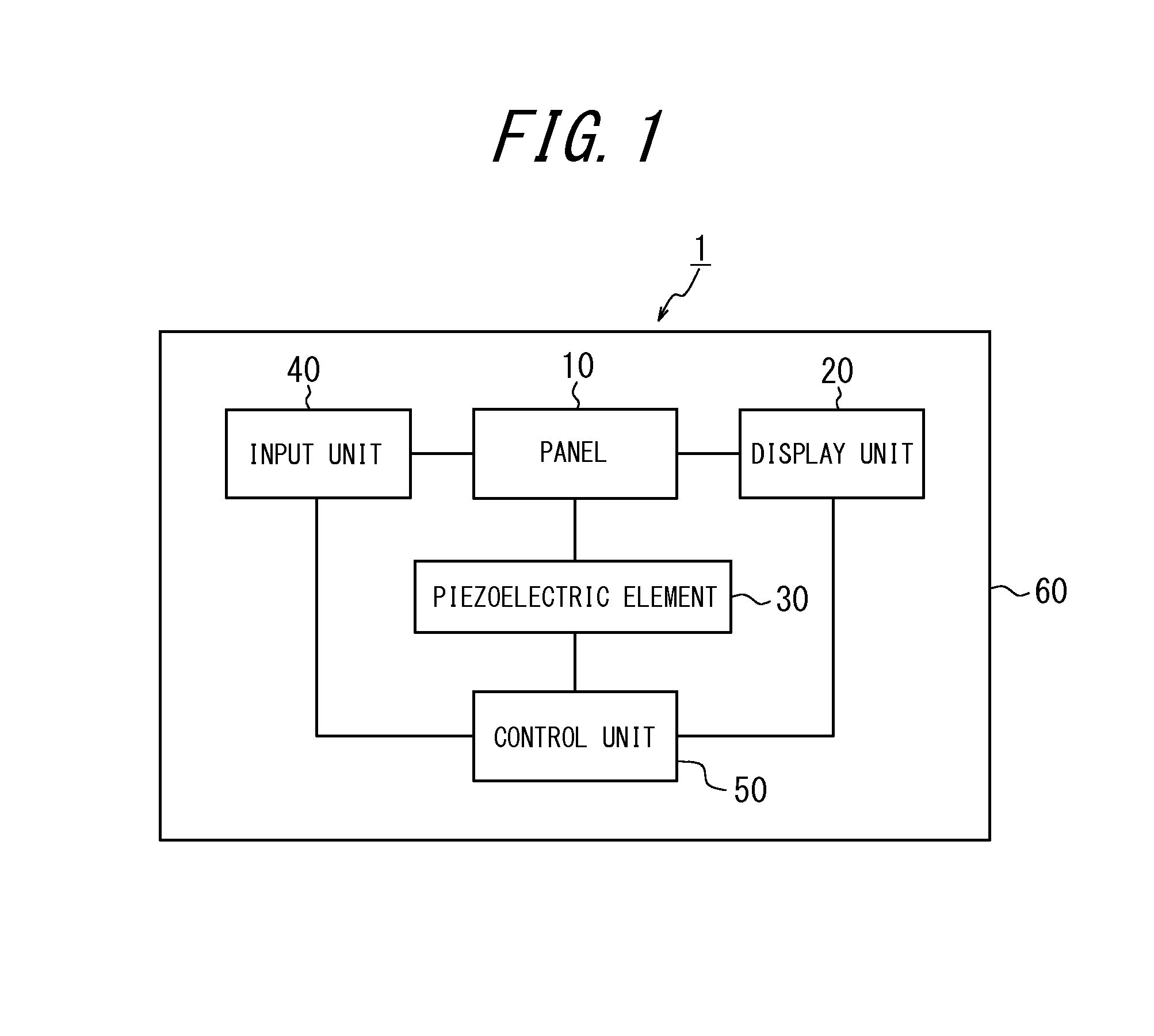
[0044]FIG. 3 illustrates diagrams of a housing structure of the electronic device 1 according to the first embodiment. FIG. 3(a) is a front view, and FIG. 3(b) is a cross-sectional view taken from line b-b of FIG. 3(a). The electronic device 1 illustrated in FIG. 3 is a smart phone having the touch panel constituted by using a glass plate serving as the panel 10 disposed on a front face of a housing 60 (for example, a metallic or resin case). A circuit board 52 having the panel 10, the input unit 40 and the control unit 50 provided thereto is supported by the housing 60. The input unit 40 is an operation key inserted into an opening 310 provided on the housing 60.

[0045]The input unit 40 serving as the operation key is a movable input means for generating an input signal from an electric contact generated when pressed down by the user. Therefore, a movable part allows a certain amount of play. However, when the operation key is inserted in an opening of the panel 10, for example, sin...

second embodiment

[0053]FIG. 5 illustrates diagrams of a housing structure of the electronic device 1 according to a second embodiment. FIG. 5(a) is a front view, FIG. 5(b) is a cross-sectional view taken from line b-b of FIG. 5(a), and FIG. 5(c) is a cross-sectional view taken from line c-c of FIG. 5(a). The electronic device 1 illustrated in FIG. 5 is a folding mobile phone having the cover panel (acrylic panel) for protecting the display unit 20 and serving as the panel 10 disposed on the front face of the housing 60 on the upper side thereof. According to the second embodiment, a reinforcement member 80 is disposed between the panel 10 and the piezoelectric element 30. The reinforcement member 80 is, for example, a resin plate including a sheet metal or glass fiber. That is, the electronic device 1 according to the second embodiment includes the piezoelectric element 30 and the reinforcement member 80 attached to each other by the joint member 70 and the reinforcement member 80 and the panel 10 a...


PUM


Abstract

The electronic device including a piezoelectric element, a vibration plate having the piezoelectric element fixed thereto for generating air conduction sound by vibrating the piezoelectric element and sound to be transmitted by vibrating a part of a human body, a housing having the vibration plate fixed thereto, and an operation key provided to the housing, makes vibration of the vibration plate not likely to be transmitted to the operation key.

Description

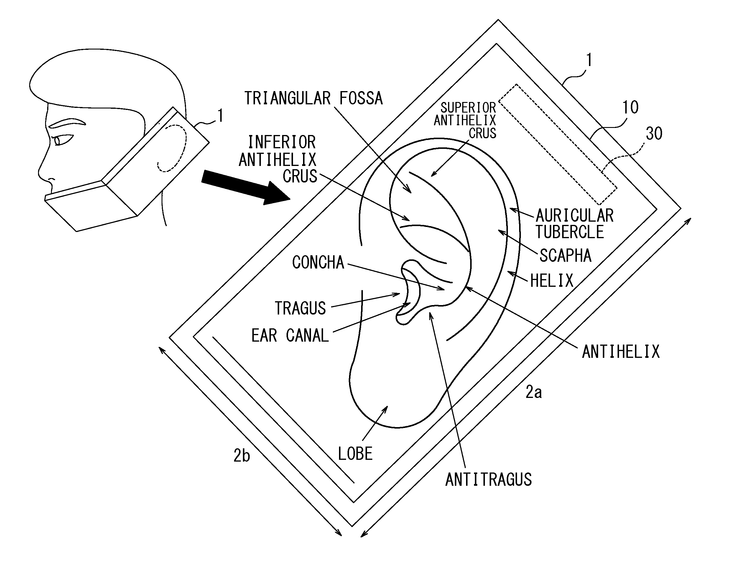
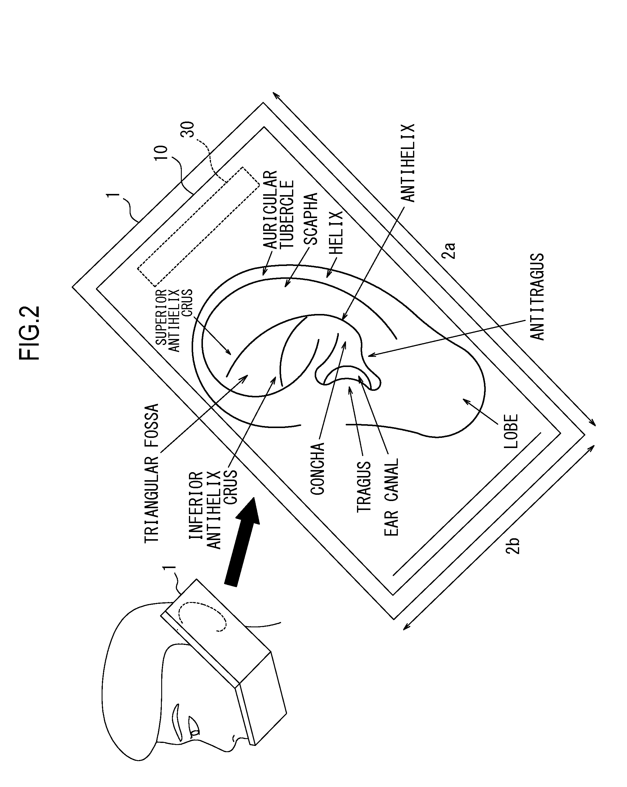
CROSS REFERENCE TO RELATED APPLICATION[0001]This application claims priority to and the benefit of Japanese Patent Application No. 2012-089203 (filed on Apr. 10, 2012), the entire content of which is incorporated herein by reference.FIELD[0002]The embodiments discussed herein relate to an electronic device that, by vibrating a panel by applying a predetermined electric signal (sound signal) on a piezoelectric element, transmits the vibration of the panel through a human body such that sound is transmitted to a user.BACKGROUND[0003]Patent document 1 listed below describes an electronic device such as a mobile phone that transmits the air conduction sound and bone conduction sound to the user. Patent document 1 also describes that the air conduction sound is sound transmitted to the auditory nerve of the user as vibration of the air caused by vibration of an object is transmitted to the eardrum through the ear canal and vibrates the eardrum. Patent document 1 further describes that th...

Claims


Application Information

Patent Timeline
Patent Type & Authority Applications(United States)
IPC IPC(8): H04M1/02
CPCH04M19/047H04M1/026
Inventor NABATA, TOSHIHISAMIYANO, TOMOAKIMIZUTA, SATOSHISATO, KIYOKAZUKIHARA, AKIOKAZAMA, SHUN
Owner KYOCERA CORP
Learn More