
Resonator element, resonator, electronic device, electronic apparatus, and mobile object

a resonator and resonator technology, applied in piezoelectric/electrostrictive/magnetostrictive devices, piezoelectric/electrostriction/magnetostriction machines, oscillators, etc., can solve the problem of deteriorating frequency adjustment accuracy, degrading the production yield of the resonator, and unable to achieve the pulling sensitivity sufficient to compensate the deterioration of frequency adjustment accuracy. , to achieve the effect o

Active Publication Date: 2013-10-03
SEIKO EPSON CORP
View PDF4 Cites 16 Cited by
  • Summary
  • Abstract
  • Description
  • Claims
  • Application Information

AI Technical Summary

Benefits of technology

The patent text describes a technology for improving the performance of a high-frequency resonator element. By using a thick electrode, reduced ohmic loss can be achieved, which helps to maintain the principle vibration. Additionally, by using a substrate with different displacement directions, energy confinement can be improved and the capacitance ratio of the resonator element can be reduced. This results in a broader pull range and improved signal-to-noise ratio for voltage controlled oscillators. Ultimately, this technology can lead to a more reliable mobile object.

Problems solved by technology

However, if the thickness of the vibrating portion is decreased for achieving the higher frequency, there arises a problem that the adjustment sensitivity of the frequency increases to degrade the frequency tuning accuracy, and thus the production yield of the resonator is degraded.
However, if the capacitance ratio γ can be decreased by cutting out the four corners of the excitation electrode to achieve the area ratio of 95% through 98% as disclosed in Document 1 mentioned above, although it is sufficient for the electrical characteristics of the temperature compensated oscillator, in the resonator used for the voltage controlled oscillator, there is a problem that it is unachievable to obtain the pulling sensitivity sufficient to compensate the frequency adjustment accuracy thus deteriorated.

Method used


Image

  • Resonator element, resonator, electronic device, electronic apparatus, and mobile object
  • Resonator element, resonator, electronic device, electronic apparatus, and mobile object
  • Resonator element, resonator, electronic device, electronic apparatus, and mobile object

Examples


Embodiment Construction

[0057]Hereinafter, a resonator element, a resonator, an electronic device, an electronic apparatus, and a mobile object according to the invention will be explained in detail based on the preferred embodiments shown in the accompanying drawings.

1. Resonator Element

[0058]Firstly, a resonator element according to an embodiment of the invention will be explained.

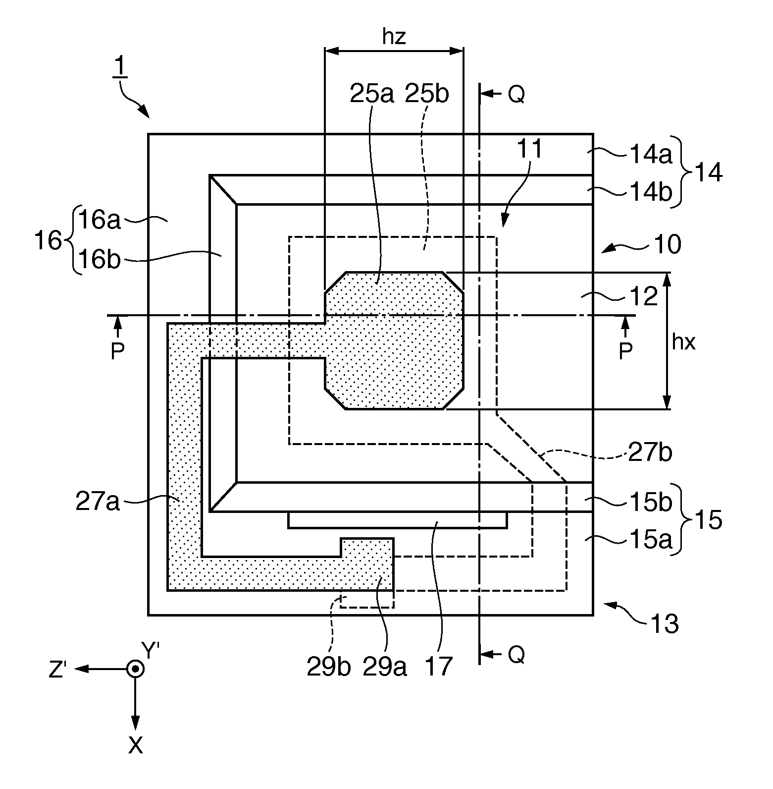
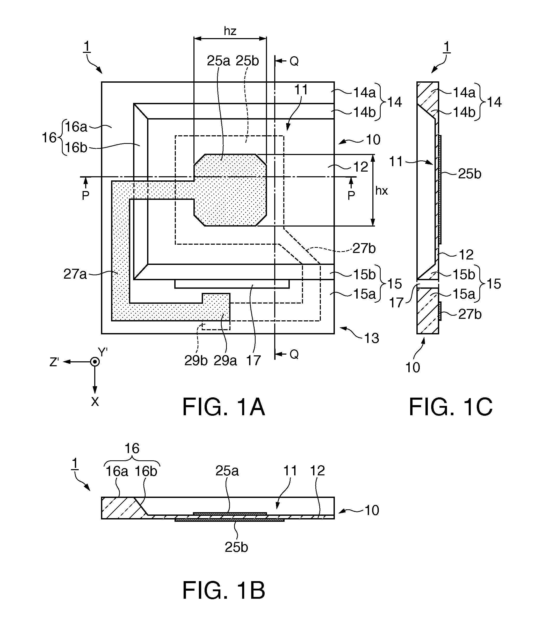
[0059]FIGS. 1A through 1C are schematic diagrams showing a configuration of a resonator element according to an embodiment of the invention, wherein FIG. 1A is a plan view of the resonator element, FIG. 1B is a P-P cross-sectional view of FIG. 1A, and FIG. 1C is a Q-Q cross-sectional view of FIG. 1A.

[0060]The resonator element 1 is provided with a substrate 10 having a vibrating section 12 and a thick-wall section 13 integrated with the vibrating section 12 and having a thickness larger than the thickness of the vibrating section 12, a first excitation electrode 25a and a second excitation electrode 25b formed on the respective...


PUM


Abstract

A resonator element includes a substrate vibrating in a thickness-shear vibration mode, a first excitation electrode disposed on one principal surface of the substrate, and has a shape obtained by cutting out four corners of a quadrangle, and a second excitation electrode disposed on the other principal surface of the substrate, and a ratio (S2 / S1) between the area S1 of the quadrangle and the area S2 of the first excitation electrode fulfills 87.7%≦(S2 / S1)<95.0%.

Description

BACKGROUND[0001]1. Technical Field[0002]This invention relates to a resonator element for exciting a thickness-shear vibration, a resonator, an electronic device, an electronic apparatus, and a mobile object.[0003]2. Related Art[0004]An AT-cut quartz crystal resonator for exciting a thickness-shear vibration as a vibration mode of the principal vibration is suitable for miniaturization and higher frequency, and has a frequency-temperature characteristic showing an excellent cubic curve, and is therefore used in a variety of fields such as an oscillator and electronic equipment. In particular, in recent years, due to the progress in speeding up of the processing speed of transmission communication equipment and OA equipment, or increase in capacity of communication data and a processing amount, a demand of increase in frequency to the AT-cut quartz crystal resonator as a reference frequency signal source used therefor is increasing. In general, in order to realize the AT-cut quartz c...

Claims


Application Information

Patent Timeline
Patent Type & Authority Applications(United States)
IPC IPC(8): H01L41/047H03B5/32
CPCH01L41/047H03H9/02157H03H9/17H03B5/32H03H3/02H03H9/0542H03H9/1021H03H9/13H03H9/19H03H9/177H10N30/87H10N30/88
Inventor ISHII, OSAMUMORITA, TAKAO
Owner SEIKO EPSON CORP
Learn More