
Amplifying device and method for controlling the same

a technology of amplifying devices and methods, applied in amplifiers, amplifier modifications to reduce noise influence, electrical devices, etc., can solve the problems of loss of linearity between input signals and output signals due to output saturation, and achieve the effect of low distortion characteristics and highly efficient operation of amplifying devices

Active Publication Date: 2013-10-03
NEC CORP
View PDF1 Cites 13 Cited by
  • Summary
  • Abstract
  • Description
  • Claims
  • Application Information

AI Technical Summary

Benefits of technology

The present invention is an amplifying device and method for controlling it that can achieve both low distortion and high efficiency at the same time. The technical effect is the simultaneous achievement of these two goals.

Problems solved by technology

Here, if an output signal voltage exceeds the power supply voltage of the power amplifier, the linearity between the input signal and the output signal is lost due to the output saturation arising.

Method used


Image

  • Amplifying device and method for controlling the same
  • Amplifying device and method for controlling the same
  • Amplifying device and method for controlling the same

Examples


first exemplary embodiment

The First Exemplary Embodiment

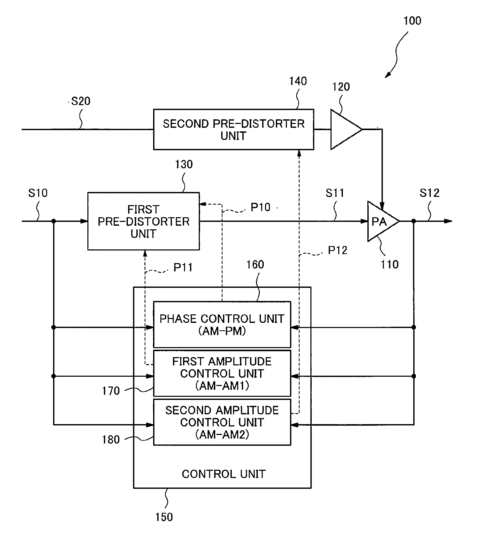
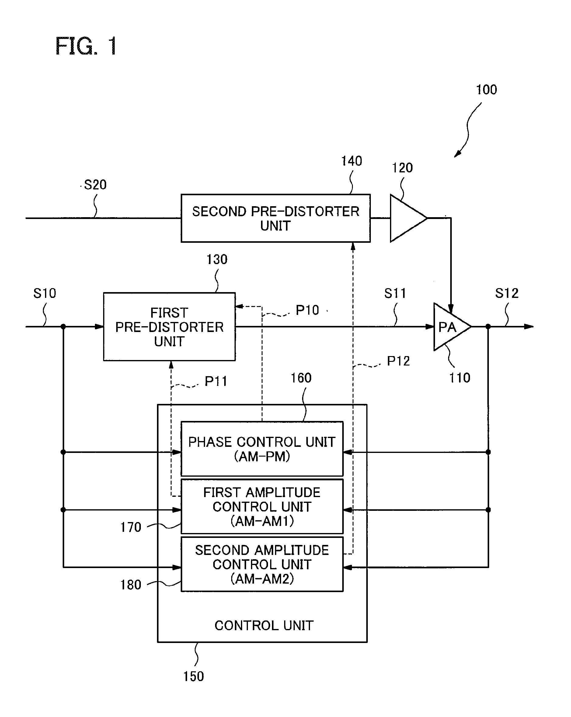
[0034]FIG. 1 is a block diagram showing a configuration of an amplifying device 100 in accordance with the first exemplary embodiment of the present invention. The amplifying device 100, which is an amplifying device with Envelope Tracking system, includes a power amplifier (PA) 110 and a power supply voltage modulation unit 120 modulating a power supply voltage of the power amplifier 110. The amplifying device 100 further includes a first pre-distorter unit 130 disposed in the preceding stage of the power amplifier 110, a second pre-distorter unit 140 disposed in the preceding stage of the power supply voltage modulation unit 120, and a control unit 150. The first pre-distorter unit 130 outputs to the power amplifier (PA) 110 a modulated signal S11 obtained by adding a phase compensation amount and an amplitude adjustment amount to an input signal S10. The second pre-distorter unit 140 obtains amplitude information S20 on the input signal of the amplif...

second exemplary embodiment

The Second Exemplary Embodiment

[0057]Next, the second exemplary embodiment of the present invention will be described. FIG. 6 is a block diagram showing the configuration of an amplifying device 200 in accordance with the present exemplary embodiment. The amplifying device 200, which is an amplifying device with Envelope Tracking system, includes the power amplifier (PA) 110 and the power supply voltage modulation unit 120 modulating the power supply voltage of the power amplifier 110. The amplifying device 200 further includes the first pre-distorter unit 130 disposed in the preceding stage of the power amplifier 110, the second pre-distorter unit 140 disposed in the preceding stage of the power supply voltage modulation unit 120, and a control unit 250.

[0058]The first pre-distorter unit 130 outputs to the power amplifier (PA) 110 the modulated signal S11 obtained by adding a phase compensation amount and an amplitude adjustment amount to the input signal S10. The second pre-distor...


PUM


Abstract

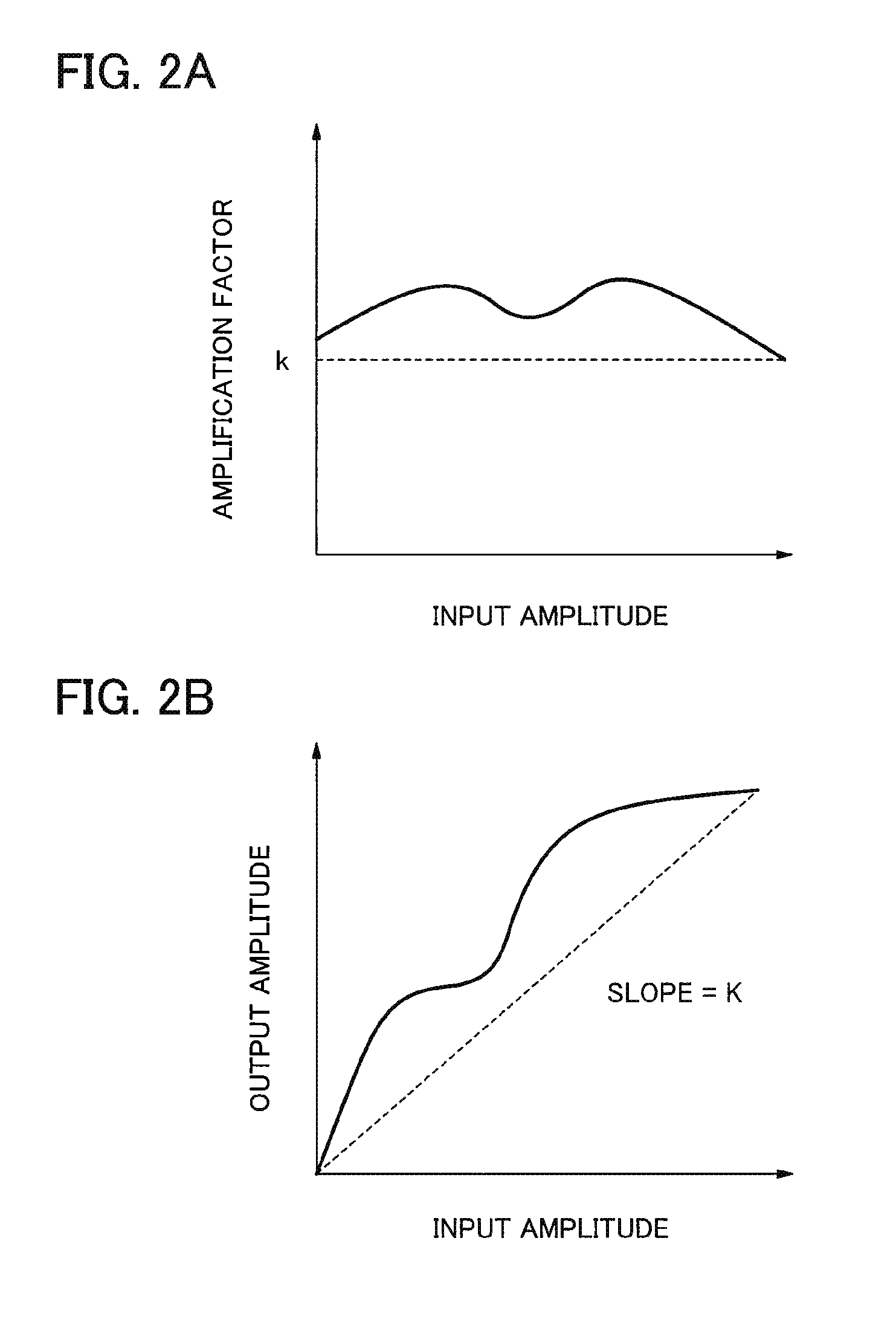
It is difficult to realize the low distortion characteristics and the highly-efficient operation of the amplifying device simultaneously, therefore, an amplifying device according to an exemplary aspect of the invention includes a first pre-distorter unit outputting a modulated signal obtained by adding a phase compensation amount and an amplitude adjustment amount to an input signal; a power amplifier inputting the modulated signal and outputting an output signal obtained by amplifying the modulated signal; a power supply voltage modulation unit modulating a power supply voltage of the power amplifier; a second pre-distorter unit controlling the power supply voltage modulation unit on the basis of amplitude information on the input signal; and a control unit controlling an operation of the first pre-distorter unit and the second pre-distorter unit; wherein the control unit includes a phase control unit controlling the phase compensation amount by using a phase coefficient, a first amplitude control unit controlling the amplitude adjustment amount by using a first amplitude coefficient, and a second amplitude control unit controlling the operation of the second pre-distorter unit by using a second amplitude coefficient; and wherein the first amplitude control unit cooperates with the second amplitude control unit so that an amplitude amplification factor may become constant which is a ratio of an amplitude of the output signal to an amplitude of the input signal.

Description

DESCRIPTION[0001]1. Technical Field[0002]The present invention relates to amplifying devices and methods for controlling the same, in particular, to an amplifying device and a method for controlling the same having highly-efficient and low distortion characteristics.[0003]2. Background Art[0004]In a transmitter used in a base station of a radio communications system, an amplifying device having high power efficiency is required in order to miniaturize the transmitter and reduce its power consumption. As technologies to realize high efficiency of the amplifying device, technologies are known in which the power consumption can be reduced by controlling a power supply voltage depending on an input signal. A particularly effective system of them is an Envelope Tracking system.[0005]The Envelope Tracking system is a system in which a power supply voltage of an amplifier such as a power amplifier and the like is changed depending on the amplitude of an input signal. Since the electric pow...

Claims


Application Information

Patent Timeline
IPC IPC(8): H03F1/32H03F1/02
CPCH03F1/0211H03F1/3247H03F1/3288H03F2201/3233H03F1/02H03F3/24
Inventor TANIO, MASAAKI
Owner NEC CORP
Learn More