Tool path part program modification system of NC machine tool

a program modification and tool path technology, applied in the field of numerical control systems, can solve the problems of excessive air cut generation, many automation systems neglect to consider, etc., and achieve the effect of shortening the processing tim

Active Publication Date: 2013-09-26
DN SOLUTIONS CO LTD
View PDF8 Cites 20 Cited by
  • Summary
  • Abstract
  • Description
  • Claims
  • Application Information

AI Technical Summary

Benefits of technology

[0010]An aspect of the disclosure has been made in an effort to solve the aforementioned problem, and an object of the disclosure is to shorten a processing time by individualizing a transition path (a retreat path, a movement path, and an approach path of a tool), which is uniformly generated in an automated manner, correspondingly to each situation, and optimizing the path.
[0019]As described above, an aspect of the present disclosure serves to reduce the overall processing time by shortening a transfer time of the consecutive rapid transfer processing block, and provides a function of automatically increasing efficiency of a processing program without intervention of a user using the three-dimensional simulator unit (400) and the tool path modification module unit (300).

Problems solved by technology

However, substantially, in addition to the actual cutting processes, minimizing air cut is another element that determines efficiency of the tool path, but is a part that many automation systems neglect to consider.
This manner has an advantage of quickly generating the processing program, but causes a problem in that the air cut is excessively generated.

Method used


Image

  • Tool path part program modification system of NC machine tool
  • Tool path part program modification system of NC machine tool
  • Tool path part program modification system of NC machine tool

Examples


Embodiment Construction

[0038]Hereinafter, an operational principle with respect to an exemplary embodiment of the disclosure will be described in detail with reference to the accompanying drawings and descriptions. However, the drawings illustrated below and the descriptions that will be described below are preferred implementation methods among various methods for effectively explaining characteristics of the disclosure, but the embodiment of the disclosure is not limited only to the below drawings and the descriptions.

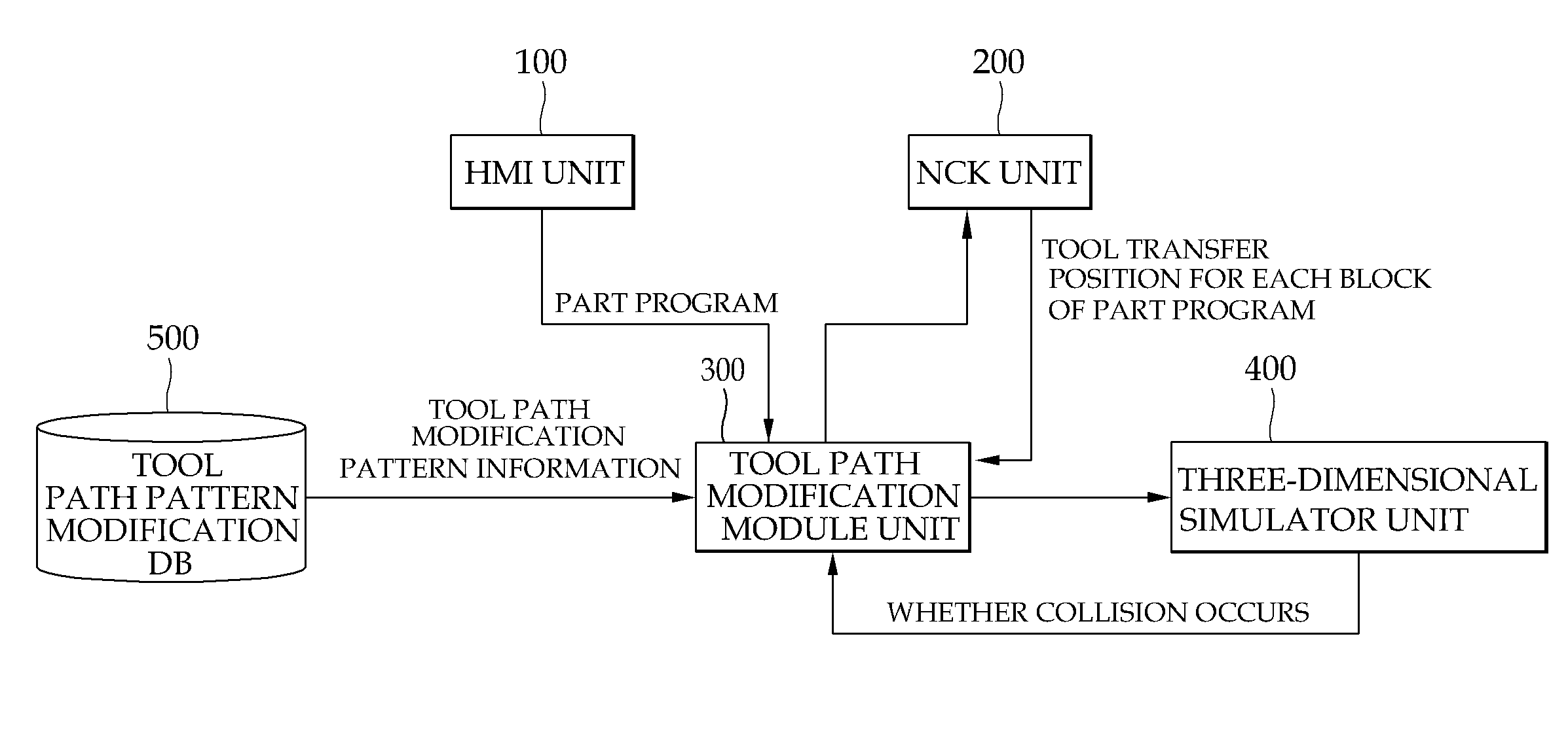
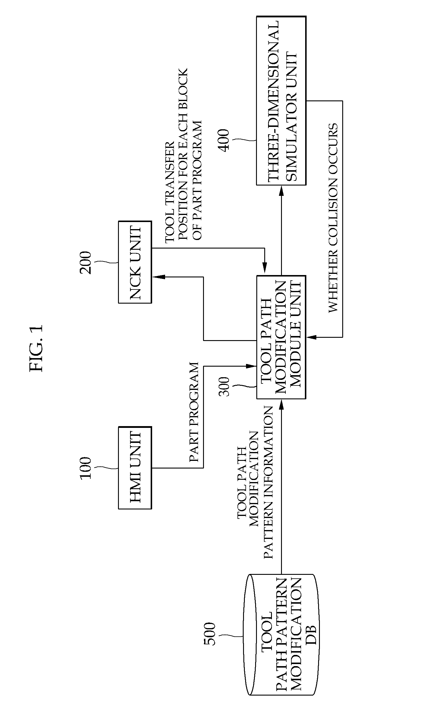
[0039]Hereinafter, an exemplary embodiment according to an aspect of the disclosure will be described in detail with reference to the accompanying drawings. In the below description, a ‘consecutive rapid transfer processing block group’ is defined as a group of a plurality of processing blocks consecutively including the predetermined number (for example, three) or more of rapid transfer command (G00) processing blocks.

[0040]FIG. 1 is a configuration block diagram of a tool path part progr...


PUM


Abstract

A tool path part program modification system of an NC machine tool according to an aspect of the present disclosure, includes: an HMI unit which receives a tool path part program having one or more processing blocks which automate and perform tool paths for processing a work piece by using tools of the NC machine tool; an NC kernel unit which interprets the part program inputted to the HMI unit for each processing block, and generates each processing block information; a tool path modification module unit which sequentially calls the processing block information interpreted by the NC kernel unit, and modifies a consecutive rapid transfer processing block group such that tool paths are reduced and collision between the tool and the work piece does not occur, when the consecutive rapid transfer processing block group is present in which the predetermined reference number or more of processing blocks including rapid transfer commands are consecutively included; and a simulator unit which simulates the part program for each processing block interpreted by the NC kernel unit.

Description

CROSS-REFERENCE TO RELATED APPLICATION[0001]This application is a Section 371 National Stage application of International application No. PCT / KR2011 / 008246, filed Nov. 1, 2011 and published, not in English, as WO2012 / 077910 on Jun. 14, 2012.FIELD OF THE DISCLOSURE[0002]The present disclosure relates to a numerical control system capable of reducing air cut (a state of transferring uncut tools), which is generated unnecessarily, in order to shorten a processing time of a part program which is made for automatic processing of tapping processing, lathe turning processing, and milling processing of a numerical control (NC) machine tool.BACKGROUND OF THE DISCLOSURE[0003]In general, generation of a tool path for an NC machine tool is directly made by an operator, or made by an automated manner such as a CAM, an interactive system, or the like.[0004]In a case in which the tool path is generated by automation systems such as a CAM, an interactive system, and the like, a user inputs informat...

Claims


Application Information

Patent Timeline
Patent Type & Authority Applications(United States)
IPC IPC(8): G06F17/50
CPCG05B19/4069G06F17/50G05B2219/35353
Inventor CHUNG, DAE HYUKPARK, JONG MYOUNGLEE, JOO SIK
Owner DN SOLUTIONS CO LTD
Why Eureka
Try Eureka