
System and Process for Removing Nitrogen Compounds and Odors from Wastewater and Wastewater Treatment System

a wastewater treatment system and nitrogen compound technology, applied in the direction of multi-stage water/sewage treatment, separation process, filtration separation, etc., can solve the problems of media washout in cylinders, unfavorable environmental support for metabolic needs of organisms, and high cost of discharging untreated water to municipal wastewater treatment facilities, so as to improve the fluidization of the bed material and reduce the footprint

Active Publication Date: 2013-09-19
BIOFILTER SYST
View PDF14 Cites 14 Cited by
  • Summary
  • Abstract
  • Description
  • Claims
  • Application Information

AI Technical Summary

Benefits of technology

The invention is a multi-stage bioreactor that removes nitrogenous waste and odors from wastewater using a network of aerobic and anaerobic chambers. The design provides a smaller footprint and improved fluidization of the bed material. Different parameters are measured and recorded, and the system can adjust its operation in real-time to ensure compliance. The invention can also be connected to a central monitoring station to achieve continuous water treatment and protect against unauthorized discharge of contaminated water into the environment. Overall, the invention offers a cost-effective solution for distributed wastewater treatment.

Problems solved by technology

The primary disadvantage of microbial systems (or bioreactors) is that the organisms require an environment conducive to supporting their metabolic needs.
The cost of discharging untreated water to a municipal wastewater treatment facility can be prohibitive.
Cone shaped fluidized beds (compared to straight cylinders) are more tolerant of variations in flow rates and media size uniformity, which can lead to media washout in cylinders.
Nitrates are as problematic as ammonia as a contaminant in waste streams.
These systems are expensive to operate as they must have the capacity to process surges of storm water along with the normal volume of sewage they treat.
These systems, which include septic tanks, do not require extensive sewer systems and are, generally, used in locations where access to sewage treatment plants is not practical.
Septic tanks employ physical and biological removal of organics similarly to conventional sewage treatment plant but do not have the capacity to handle large surges of wastewater.
As a result, these systems can and do discharge untreated sewage into the water table.
Problems associated with septic tanks 3800 are many.
First, they are always full.
Like septic tanks, package plants can be overloaded hydraulically during peak loading hours, after lunch is served for example, when large volumes of wastewater enter the system, forcing contaminated water to be discharged before it can be properly processed.
In rural areas where package plants and septic systems are employed, however, wastewater discharge into the environment is uncontrolled, largely unregulated and contaminants are routinely discharged into the environment.
There are no standard agricultural wastewater treatment systems on the market.
Due to the massive amounts of waste created by these facilities and the high cost of municipal-class treatment systems, agricultural waste processing systems often rely on large lagoons to provide secondary and tertiary processing of their waste.
Unfortunately, these systems are subject to failure due to overflow from heavy rains and leakage from the lagoon basin.

Method used


Image

  • System and Process for Removing Nitrogen Compounds and Odors from Wastewater and Wastewater Treatment System
  • System and Process for Removing Nitrogen Compounds and Odors from Wastewater and Wastewater Treatment System
  • System and Process for Removing Nitrogen Compounds and Odors from Wastewater and Wastewater Treatment System

Examples


Embodiment Construction

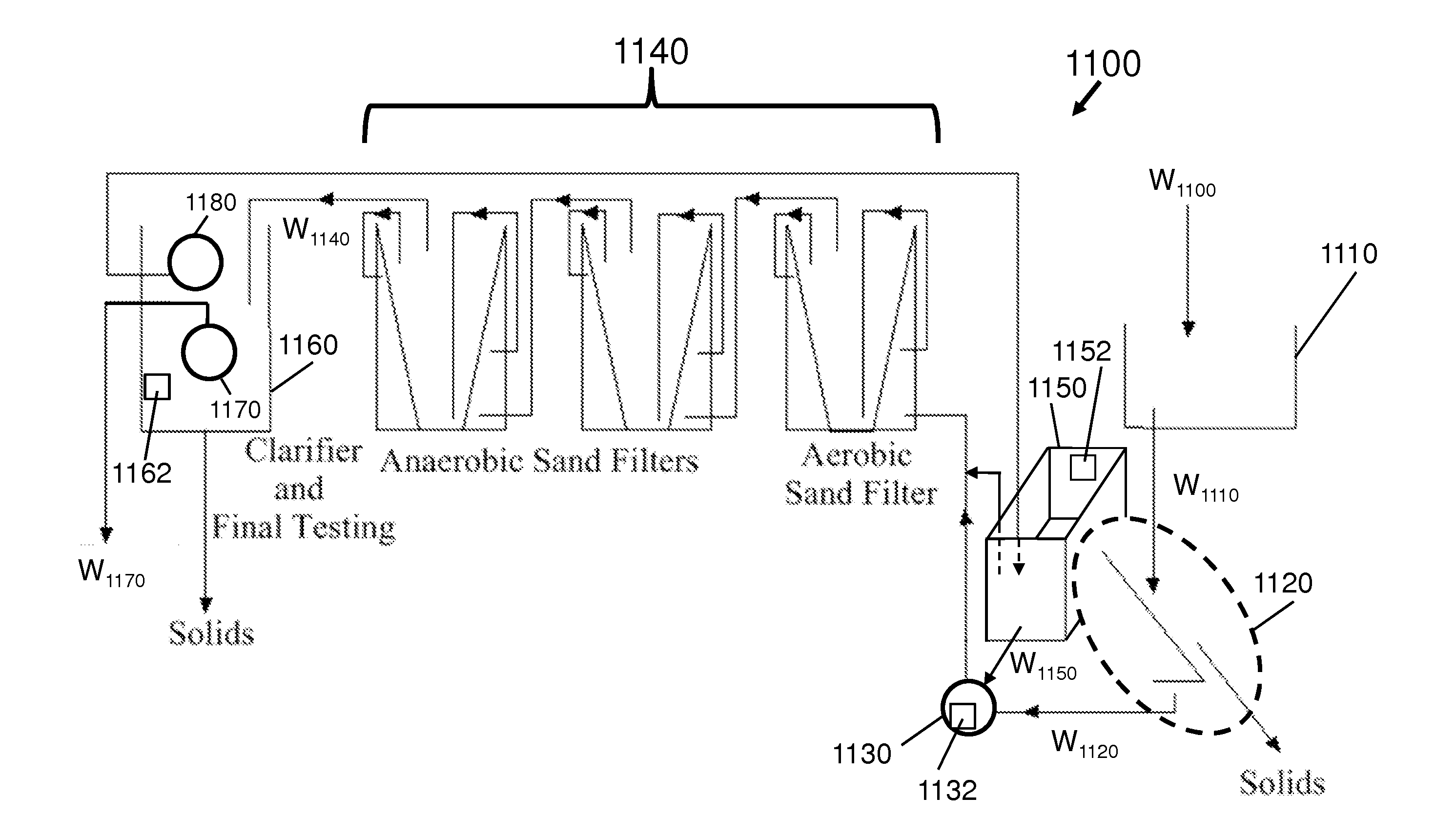
[0109]As required, detailed embodiments of the present invention are disclosed herein; however, it is to be understood that the disclosed embodiments are merely exemplary of the invention, which can be embodied in various forms. Therefore, specific structural and functional details disclosed herein are not to be interpreted as limiting, but merely as a basis for the claims and as a representative basis for teaching one skilled in the art to variously employ the present invention in virtually any appropriately detailed structure. Further, the terms and phrases used herein are not intended to be limiting; but rather, to provide an understandable description of the invention. While the specification concludes with claims defining the features of the invention that are regarded as novel, it is believed that the invention will be better understood from a consideration of the following description in conjunction with the drawing figures, in which like reference numerals are carried forwar...


PUM

PropertyMeasurementUnit
areaaaaaaaaaaa
temperatureaaaaaaaaaa
pHaaaaaaaaaa

Abstract

A wastewater treatment system includes a wastewater collection system, at least one aeration subsystem aerating the aerobic portion, and at least one filtration subsystem. The wastewater collection system has an anoxic portion, an aerobic portion downstream of the anoxic portion, an anaerobic portion downstream of the aerobic portion. The filtration subsystem includes at least one bioreacting filter receiving fluid from the aerobic portion, being operable to filter wastewater received from the aerobic portion, and discharging filtered fluid into the anoxic portion, an oxygen contactor fluidically connected between the aerobic portion and the at least one bioreacting filter and operable to diffuse oxygen into the fluid being supplied from the aerobic portion, and an oxygen supply operable to supply oxygen to the oxygen contactor.

Description

CROSS-REFERENCE TO RELATED APPLICATIONS[0001]This application:[0002]claims the priority of U.S. Provisional Patent Application Ser. No. 61 / 751,041, filed on Jan. 10, 2013;[0003]is a continuation-in-part of U.S. patent application Ser. No. 12 / 793,144, filed on Jun. 3, 2010 (which application claimed the priority to U.S. Provisional Application Ser. No. 61 / 294,521 filed on Jan. 13, 2010);[0004]is a continuation-in-part of PCT / US 11 / 20967, filed Jan. 12, 2011;[0005]is a continuation-in-part of U.S. patent application Ser. No. 13 / 240,608, filed on Sep. 22, 2011 (which application claimed the priority to U.S. Provisional Application Ser. No. 61 / 385,603 filed on Sep. 23, 2010);[0006]is a continuation-in-part of U.S. patent application Ser. No. 13 / 748,131, filed on Jan. 23, 2012,the entire disclosures of which are hereby incorporated herein by reference in their entireties.STATEMENT REGARDING FEDERALLY SPONSORED RESEARCH OR DEVELOPMENT[0007]Not ApplicableFIELD OF THE INVENTION[0008]The pre...

Claims


Application Information

Patent Timeline
Patent Type & Authority Applications(United States)
IPC IPC(8): C02F3/30
CPCC02F1/001C02F3/006C02F3/2833C02F3/302C02F2101/16C02F2101/163C02F3/085C02F2103/20C02F2209/006C02F2209/008C02F2303/02C02F3/30B01F5/0057C02F2101/166Y02W10/10B01F25/10C02F3/20C02F3/303B01D21/01B01D29/117C02F1/5281C02F1/68C02F1/766C02F3/14C02F3/305C02F9/00
Inventor ROBERTSON, MARK B.O'KEEFE, DAVIDCOX, JOHN D.WHITE, DANIEL T.
Owner BIOFILTER SYST
Learn More