
Multiple patterning process for forming trenches or holes using stitched assist features

a technology of assist features and patterning process, which is applied in the direction of photomechanical treatment originals, photomechanical instruments, photomechanical equipment, etc., can solve the problems of inefficient process window of isolated features, reduced device dimensions and pitches, and unacceptable variations in topography

Active Publication Date: 2013-09-12
GLOBALFOUNDRIES US INC
View PDF4 Cites 25 Cited by
  • Summary
  • Abstract
  • Description
  • Claims
  • Application Information

AI Technical Summary

Benefits of technology

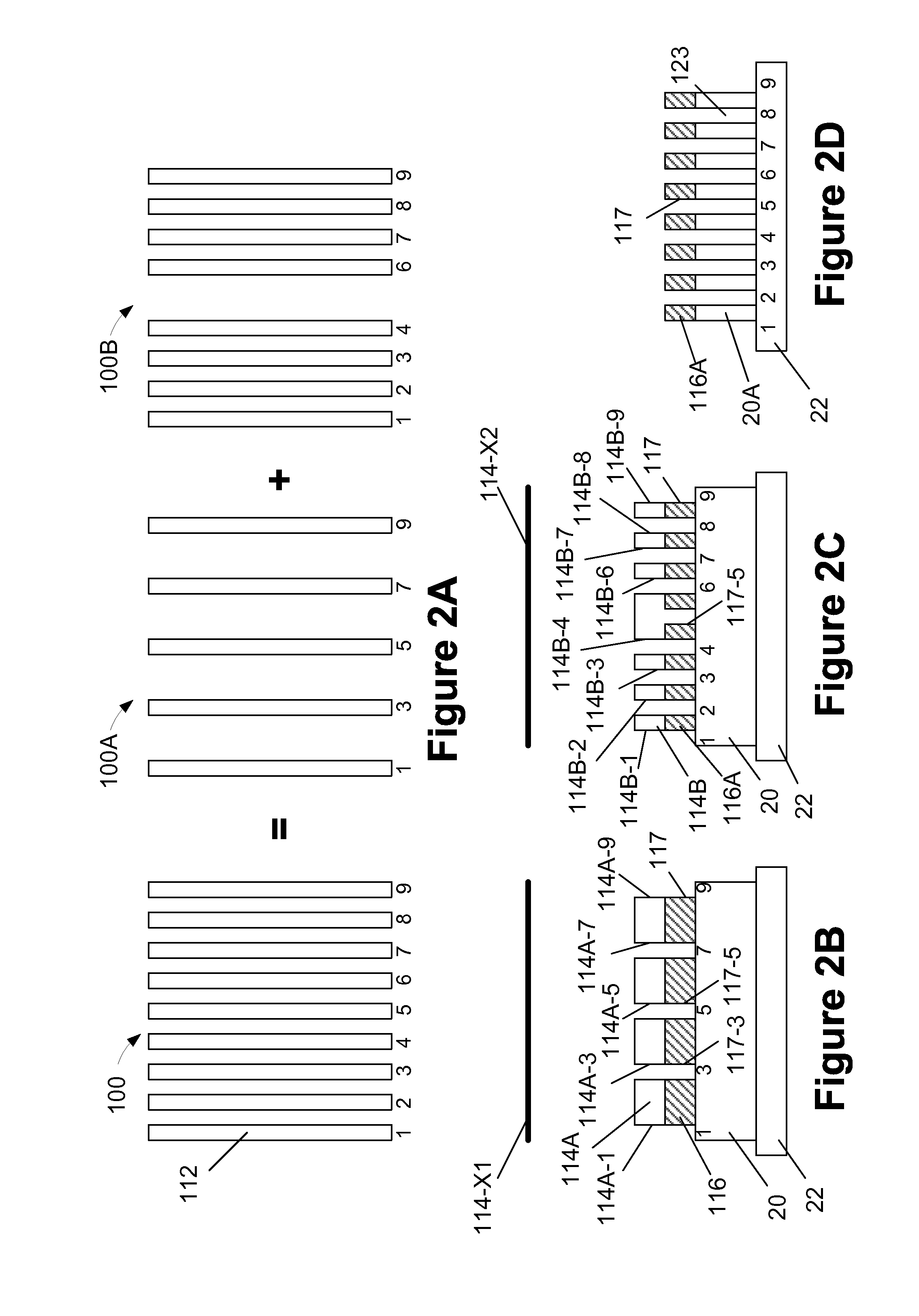
The present invention is related to the design of masks or reticles used in multiple patterning processes to create integrated circuit products. More specifically, the invention is about a method for decomposing an overall target pattern into sub-target patterns and generating the mask data information required to manufacture a set of masks for each sub-target pattern. The masks can then be used in a lithography system to create the desired patterns on a semiconductor wafer. The technical effect of this invention is to improve the accuracy and efficiency of the patterning process for integrated circuit products.

Problems solved by technology

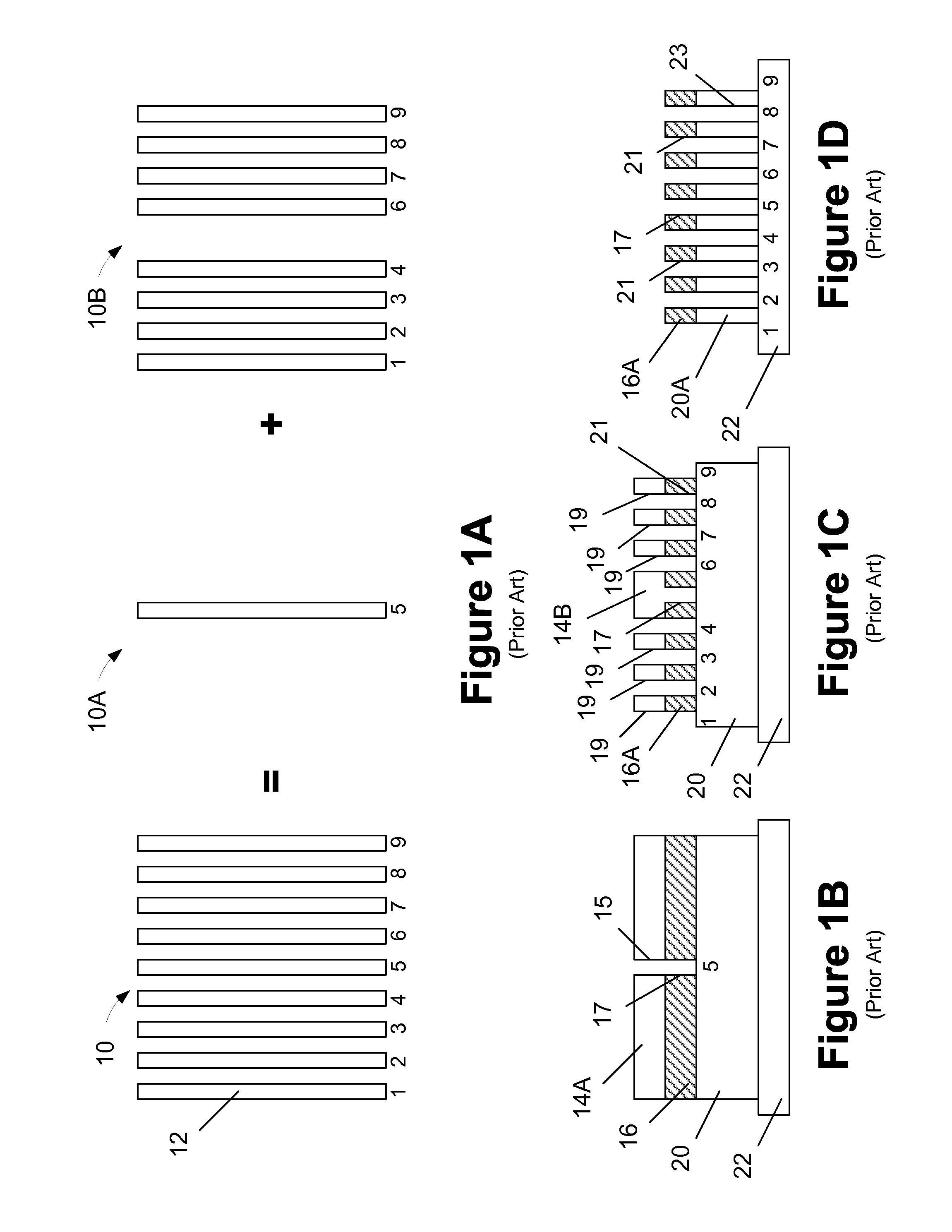
However, in recent years, device dimensions and pitches have been reduced to the point where existing photolithography tools, e.g., 193 nm wavelength photolithography tools, cannot form single patterned mask layers with all of the features of the overall target pattern.
There are several factors that cause such process variations, such as interference between light beams transmitted through adjacent patterns, resist processes, the reflection of light from adjacent or underlying materials or structures, unacceptable variations in topography, etc.
However, in some applications, the packing density and design rules for a particular circuit are such that there is no room for re-targeting certain features.
As a result, in those situations, isolated features may have a very inefficient process window and only SRAFs may be employed to improve the process window of such features.
While such SRAFs do improve the process window, they may give rise to reduced depth-of-focus issues.
The design and manufacture of reticles used in such photolithography processes is a very complex and expensive undertaking as such masks must be very precise and must enable the repeated and accurate formation of a desired pattern in the underlying layer of material (for an etching process).

Method used


Image

  • Multiple patterning process for forming trenches or holes using stitched assist features
  • Multiple patterning process for forming trenches or holes using stitched assist features
  • Multiple patterning process for forming trenches or holes using stitched assist features

Examples


Embodiment Construction

[0022]Various illustrative embodiments of the invention are described below. In the interest of clarity, not all features of an actual implementation are described in this specification. It will of course be appreciated that in the development of any such actual embodiment, numerous implementation-specific decisions must be made to achieve the developers' specific goals, such as compliance with system-related and business-related constraints, which will vary from one implementation to another. Moreover, it will be appreciated that such a development effort might be complex and time-consuming, but would nevertheless be a routine undertaking for those of ordinary skill in the art having the benefit of this disclosure.

[0023]The present subject matter will now be described with reference to the attached figures. Various structures, systems and devices are schematically depicted in the drawings for purposes of explanation only and so as to not obscure the present disclosure with details ...


PUM


Abstract

One illustrative method disclosed herein involves identifying an overall target pattern comprised of at least one hole-type feature, decomposing the overall target pattern into at least a first sub-target pattern and a second sub-target pattern, wherein the first sub-target pattern and the second sub-target pattern each comprise at least one common hole-type feature, generating a first set of mask data information corresponding to the first sub-target pattern, and generating a second set of mask data information corresponding to the second sub-target pattern.

Description

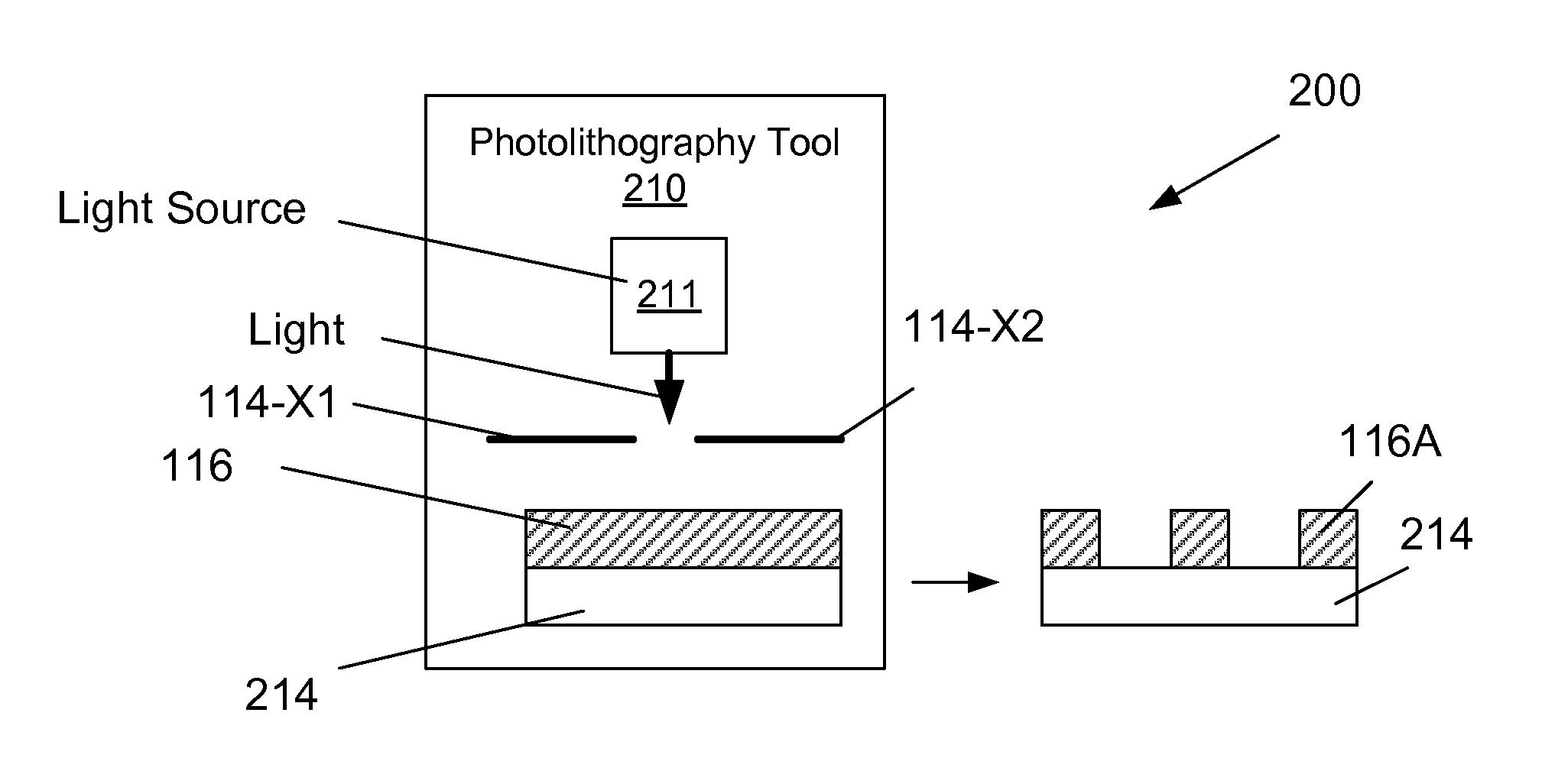
BACKGROUND OF THE INVENTION[0001]1. Field of the Invention[0002]Generally, the present disclosure relates to the manufacture of sophisticated semiconductor devices, and, more specifically, to the design of masks or reticles for use in multiple patterning processes, such as double patterning processes, that are performed to form hole-type or trench-type features, and the use of such masks or reticles in various photolithography systems to manufacture integrated circuit products.[0003]2. Description of the Related Art[0004]Photolithography is one of the basic processes used in manufacturing integrated circuit products. At a very high level, photolithography involves (1) forming a layer of light or radiation-sensitive material, such as photoresist, above a layer of material or a substrate, (2) selectively exposing the radiation-sensitive material to a light generated by a light source (such as a DUV or EUV source) to transfer a pattern defined by a mask or reticle (interchangeable term...

Claims


Application Information

Patent Timeline
IPC IPC(8): G03F7/20G06F17/50
CPCG03F7/70G03F1/76G03F1/68G03F1/70
Inventor SUN, YUYANGCHEN, NORMAN S.LIU, JIAN
Owner GLOBALFOUNDRIES US INC
Learn More