Extraction of metals

Inactive Publication Date: 2013-09-12
INFINITY CHEM ENG
View PDF10 Cites 2 Cited by
  • Summary
  • Abstract
  • Description
  • Claims
  • Application Information

AI Technical Summary

Benefits of technology

This patent describes a method and device for producing metals using a process called ion exchange. The invention provides a method where a metallic element is generated from a metal ion in a substantially inert environment. This can be achieved by creating a conductive, but chemically neutral solution that circulates within a cathode chamber. The invention also includes a metal extractor that separates cation and anion ion exchange processing cells, with the cathode chamber having a substantially inert environment for generating metallic elements. This method and device can provide a more efficient and controlled way to produce metals.

Problems solved by technology

Regrettably however, the use of the above conventional electrolysis process (with water as the medium or the electrolyte solution—an aqueous based electrolyte) is not appropriate if the metal being produced (extracted) is an active metal.
However, electrolysis processes that use non-aqueous electrolytes (e.g., organic solutions) are very inefficient in extracting and generating pure active metals.
However, the disadvantage of these types of methods is that they are very inefficient due to their poor conductivity and as a result, small quantities of metals are produced and only in the form of a thin film.
Further, the non-aqueous based ionic liquid (ionic fluid that has no water) used as the electrolyte in the electrolysis process is very costly, making the entire process inefficient and expensive.
The disadvantage of this method is the impossibility to obtain pure active metals (e.g., magnesium Mg) on the cathode due to existence of oxygen (in the aqueous electrolyte), resulting in an oxide or hydroxide compound of the active metal and in the case of magnesium Mg, high possibility exists that the ion-exchange membranes will be clogged very quickly.

Method used


Image

  • Extraction of metals
  • Extraction of metals
  • Extraction of metals

Examples


example 1

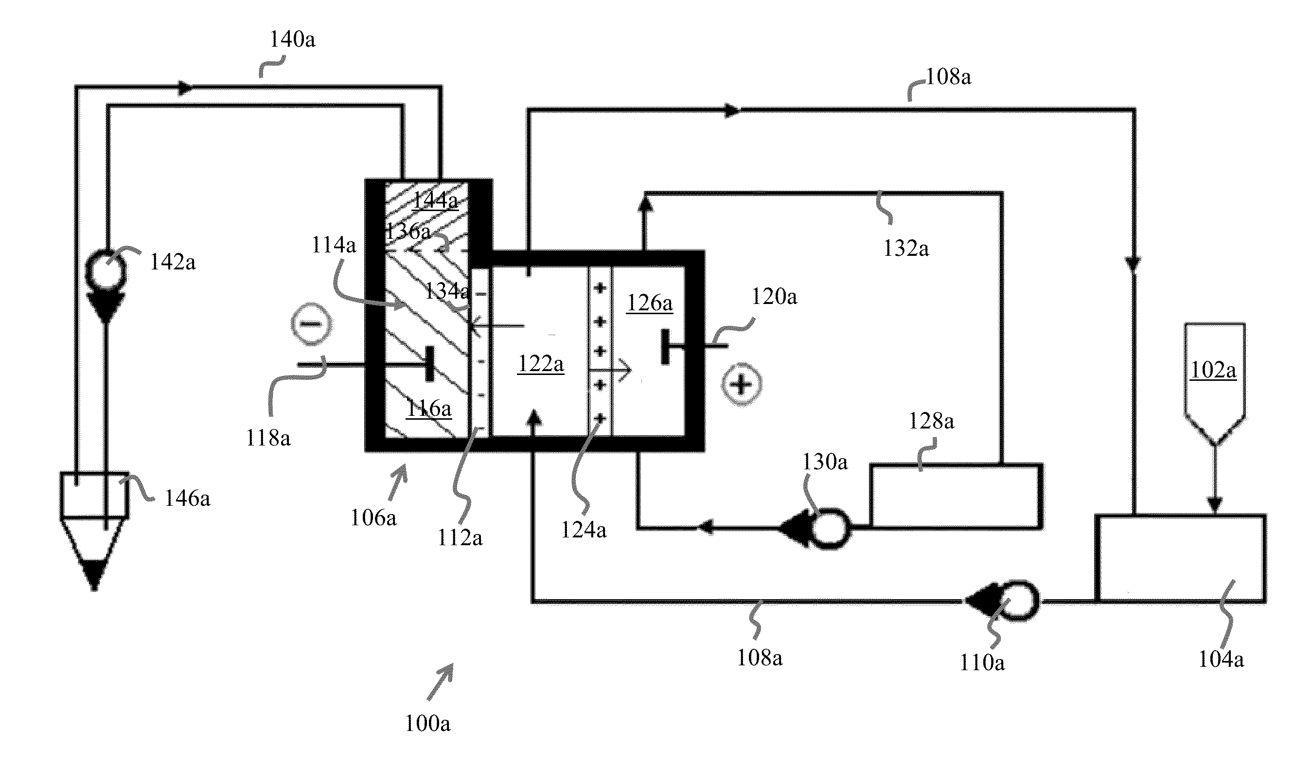
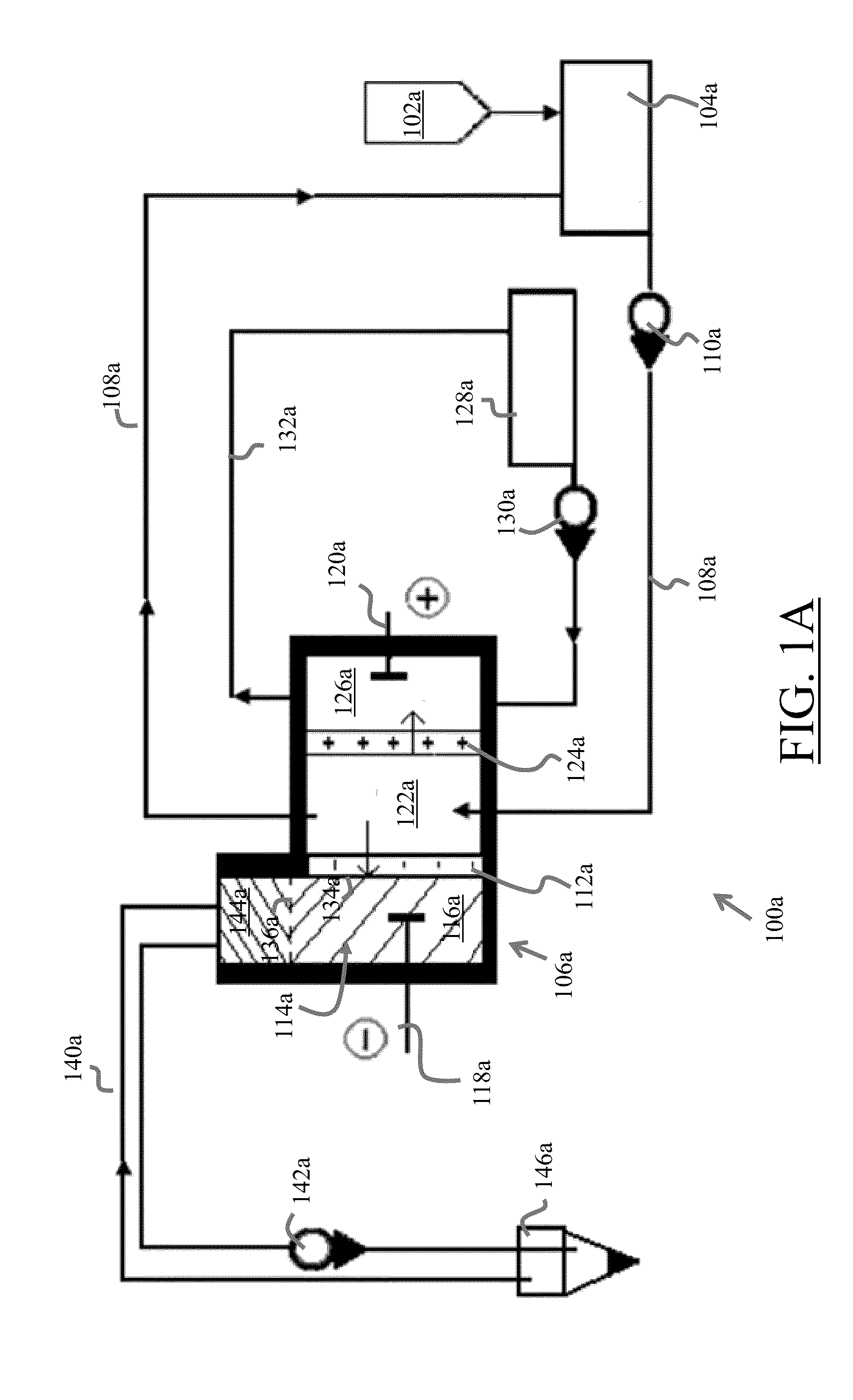
[0065]FIG. 1A illustrates the water tank of the unit where magnesium chloride water solution having 50 g / l concentration is filled.

[0066]Electro-dialyzer characteristics are as followings:

[0067]Voltage 10 V

[0068]Membrane types MK-40, MA-40, MB-1E

[0069]Membrane surface 100 cm2

[0070]Membranes numbers 3 (one membrane from each kind)

[0071]Cathode chamber volume 30 cm3

[0072]The distance between membranes 0.3 cm

[0073]Current density 0.03 A / cm2

[0074]The cathode chamber 114 of the electro-dialyzer 106 is mercury filled (liquid metal 116), which serves as a cathode 116, while a stainless steel plate (120) serves as an anode 120. A removal medium layer 144 covers the cathode 116 and functions to remove the nano-particle metallic elements M from the top skin surface 136 of the cathode chamber 114 conductive liquid 116. The aqueous electrolyte solution is filled into the circulation tank 104 with the approximate, non-limiting exemplary rate of 1 liter / minute, from which it is pumped 110a and is...


PUM

PropertyMeasurementUnit
Lengthaaaaaaaaaa
Electric chargeaaaaaaaaaa
Currentaaaaaaaaaa

Abstract

The present invention provides a substantially inert environment within a cathode chamber that is capable of generating a metallic element M from a metal ion Mz+.

Description

CROSS-REFERENCE TO RELATED APPLICATIONS[0001]This application claims the benefit of priority of the co-pending U.S. Utility Provisional Patent Application 61 / 552,269, filed Oct. 27, 2011, the entire disclosure of which is expressly incorporated by reference herein. Where a definition or use of a term in an incorporated reference is inconsistent or contrary to the definition of that term provided herein, the definition of that term provided herein applies and the definition of that term in the incorporated reference does not apply.[0002]Where a definition or use of a term in the incorporated Provisional Patent Application 61 / 552,269, filed Oct. 27, 2011 is inconsistent or contrary to the definition of that term provided herein, the definition of that term provided herein applies and the definition of that term in the incorporated Provisional Patent Application No. 61 / 552,269, filed Oct. 27, 2011 does not apply.BACKGROUND OF THE INVENTION[0003]1. Field of the Invention[0004]The presen...

Claims


Application Information

Patent Timeline
IPC IPC(8): C25C5/02C25C7/00
CPCC25C5/02C25C3/04C25C7/00
Inventor MARTOYAN, GAGIK
Owner INFINITY CHEM ENG
Why Eureka
Try Eureka