
Method for measuring current in an electric network

a technology of electric network and current measurement, applied in the direction of three-component magnetometer, electrodynamic magnetometer, magnet field offset compensation, etc., can solve the problems of high cost, reduced application range of methods, and difficulty in applying methods to service sectors or retail outlets

Active Publication Date: 2013-09-05
SMARTFUTURE
View PDF6 Cites 27 Cited by
  • Summary
  • Abstract
  • Description
  • Claims
  • Application Information

AI Technical Summary

Benefits of technology

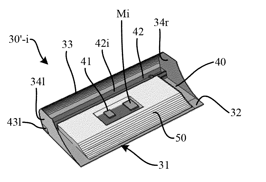
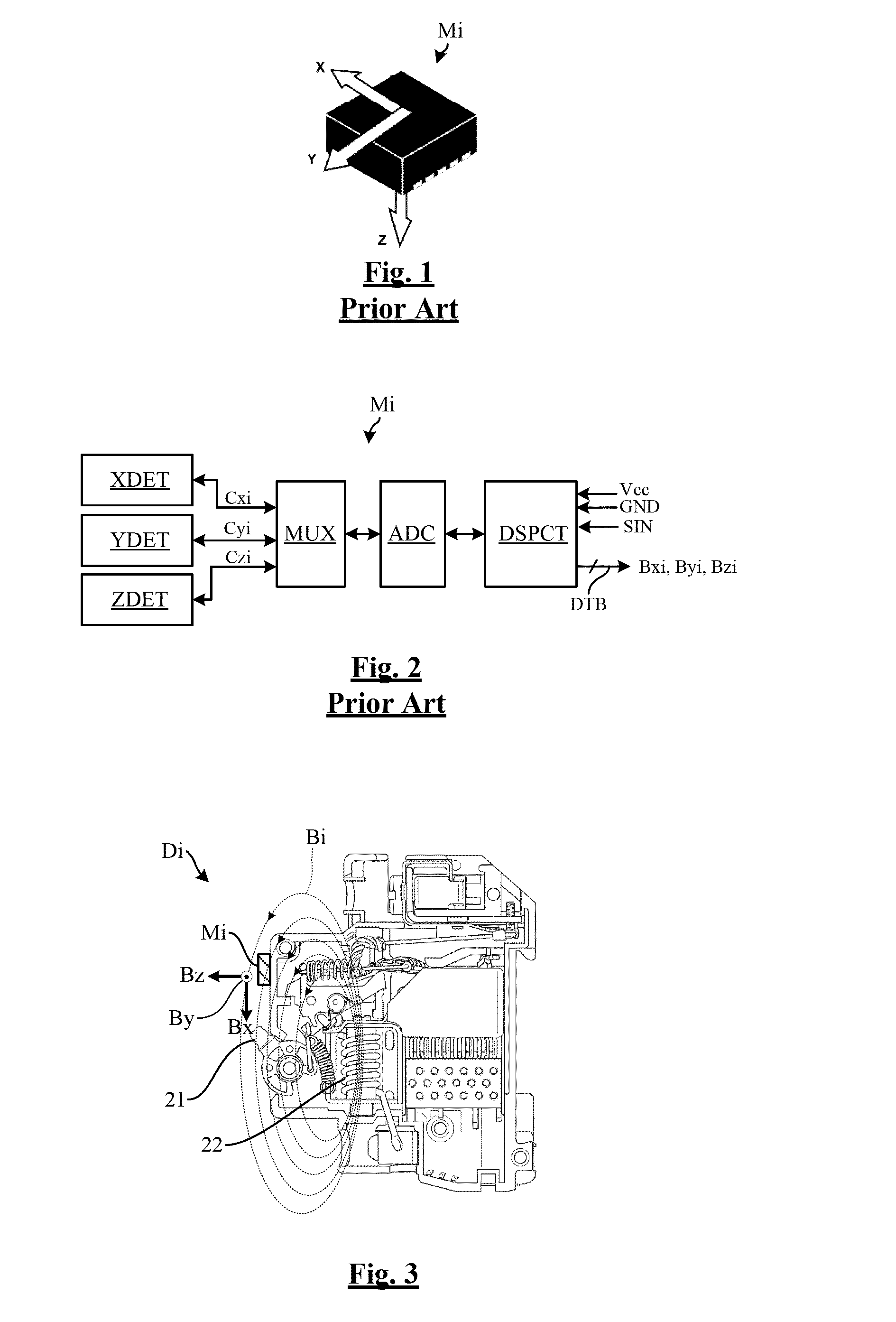
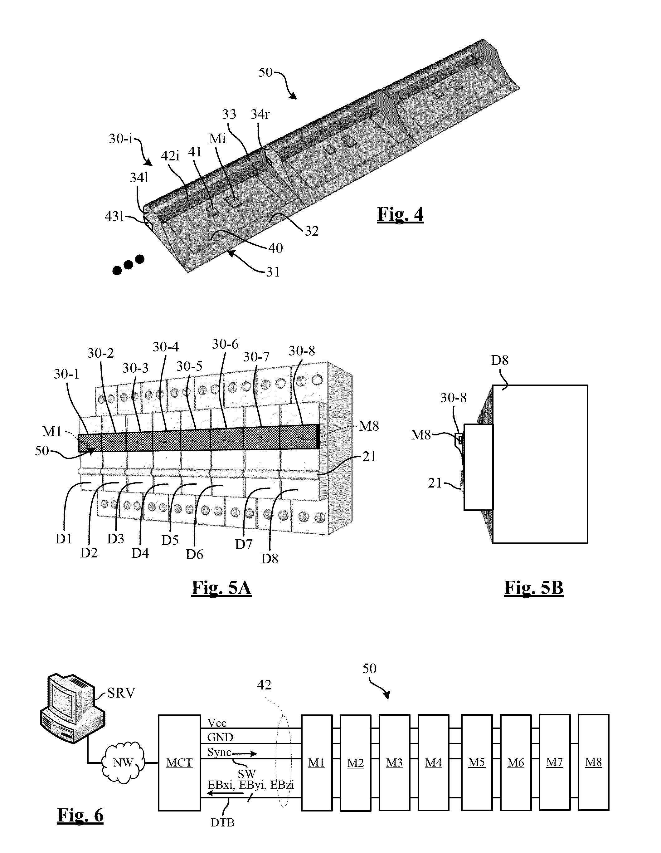
The patent text describes a method and device for measuring magnetic fields emitted by circuit breakers to detect faults. The method involves arranging a magnetic shield around the magnetometer to limit the influence of nearby circuit breakers. The device includes a second circuit breaker with a protection coil and a digital magnetometer arranged on the circuit breaker's wall to measure the magnetic field. The measured components are then corrected by subtracting from each other a fraction of the other magnetometer's measurement to neutralize magnetic interference between the two circuit breakers. The corrected components are then used to determine the current value in each electrical line. The technical effects of this patent are improved accuracy and reliability in detecting faults in electrical systems.

Problems solved by technology

Their scope of application is reduced and is limited to loads that switch only a few times a day.
These methods are thus difficult to apply to the service sector or retail outlets.
The methods involving a direct measurement are difficult to implement and expensive when they must be implemented in an existing installation.
The installation cost then greatly exceeds the savings to be made for private individuals, a small store, or a small service building.
This method is thus rarely implemented.
Moreover, circuit breakers equipped with current sensors are intended for the new property market and do not find any opening in existing buildings due to their high purchase and installation costs.
These sensors must be linked to an electronic measurement circuit and the global cost price is high.

Method used


Image

  • Method for measuring current in an electric network
  • Method for measuring current in an electric network
  • Method for measuring current in an electric network

Examples


Embodiment Construction

[0035]The present invention includes the observation that commercially available three-axis digital magnetometers can be found that are designed to measure the terrestrial magnetic field and are intended for the cellular telephone market, for applications such as compass software, metal detectors, pure silver analyzer, and the like.

[0036]These magnetometers based on MEMS are integrated onto a semiconductor chip and have, in addition to terrestrial magnetic field sensors, a measuring and control circuit, and a communication interface circuit capable of dialoging with an external controller through a data bus.

[0037]Due to the huge quantities marketed, these magnetometers have a very low cost price that is much lower than that of a magnetic field detector and its associated electronic measurement circuit, of the type mounted in electric boards to measure a current.

[0038]In addition, such magnetometers can perform synchronous measurements thanks to a synchronization input that can recei...


PUM


Abstract

A method for measuring current in an electric network comprising at least one first electric line. The method includes fitting the first line with a circuit breaker having a protection coil and having a wall traversed by a magnetic field emitted by the protection coil; arranging on the wall of the circuit breaker a synchronous three-axis digital magnetometer on a semiconductor chip; by way of the digital magnetometer, measuring at least one component of a magnetic field emitted by the coil; and determining the value of a current traversing the electric line from the measured component.

Description

BACKGROUND OF THE INVENTION[0001]Embodiments of the present invention relate to a method for measuring current in an electric network. Measuring the current consumption in an electric network enables an energy diagnosis to be made. By offering the user the possibility of monitoring its current consumption item by item, called “electrical use”, significant savings can be made.[0002]New thermal regulations encourage the use of current consumption measuring devices in service and residential buildings, by providing, in each electric board, for the estimation and the display of the consumption of the various connected appliances (heating, cooling, hot water production, lighting, cooking, sockets, and the like).[0003]Several methods for estimating electrical use are known. Certain methods involve a direct measurement by installing an electrical use submeter in the electric board, while others involve an indirect measurement by analyzing the global load curve on the network, and correlati...

Claims


Application Information

Patent Timeline
IPC IPC(8): G01R33/00
CPCG01R15/207G01R33/028G01R33/0206G01R33/0017
Inventor BERTRAND, PAUL
Owner SMARTFUTURE
Learn More