
Multichannel analytical instruments for use with specimen holders

a multi-channel analytical and specimen technology, applied in instruments, lighting and heating apparatus, optical radiation measurement, etc., can solve the problems of high manufacturing tolerance and difficulty in alignment, and achieve the effects of increasing throughput over serial sampling, compact design, and increasing portability

Active Publication Date: 2013-09-05
LAXCO
View PDF2 Cites 23 Cited by
  • Summary
  • Abstract
  • Description
  • Claims
  • Application Information

AI Technical Summary

Benefits of technology

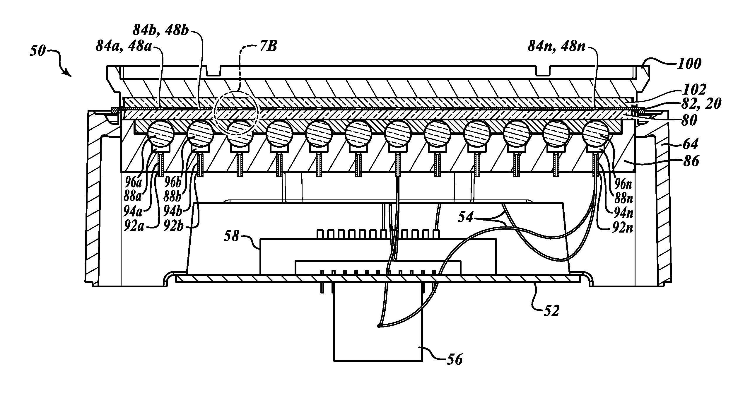
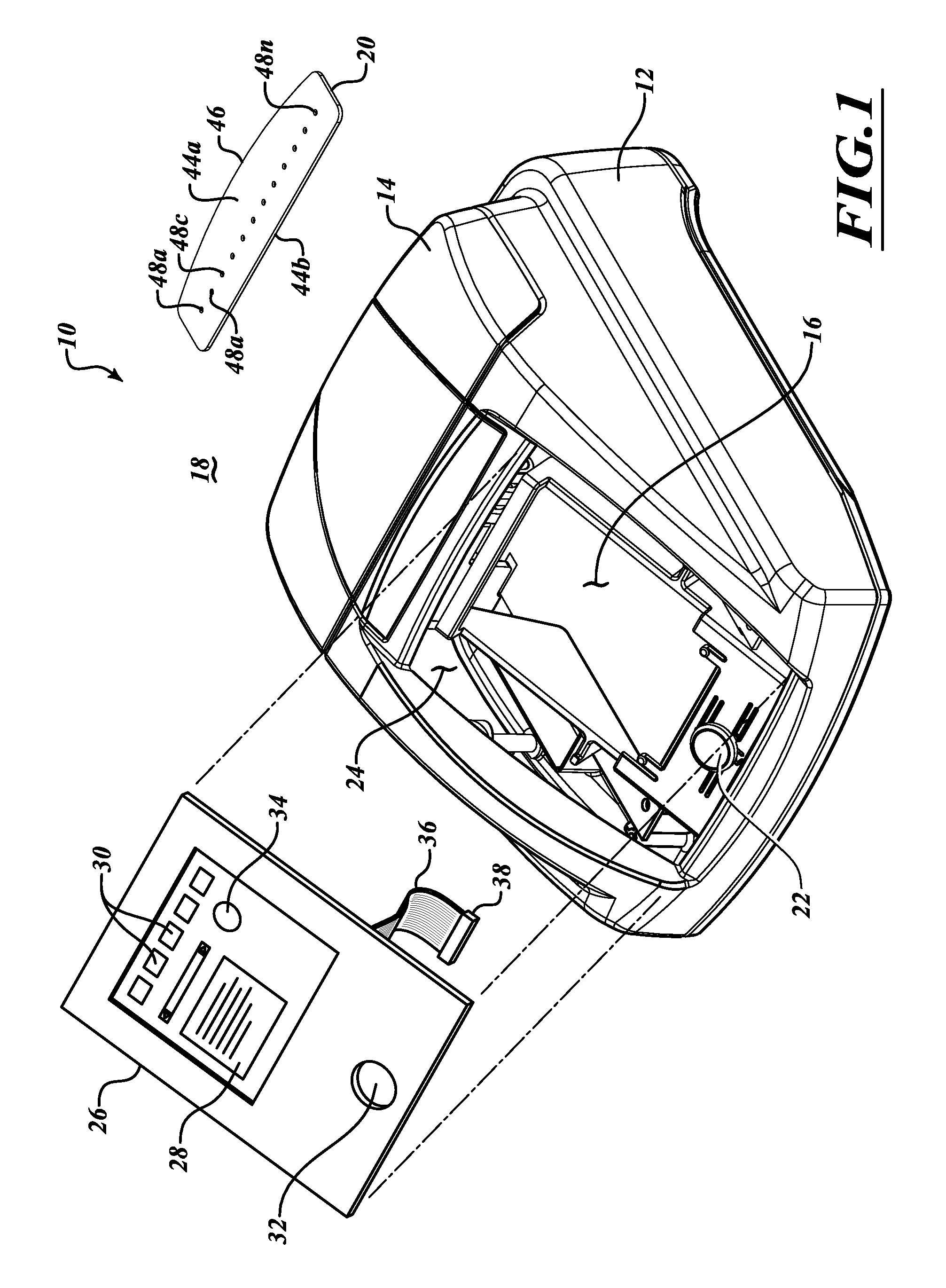
The patent describes a configuration that allows for self-aligned imaging of samples using electromagnetic energy, such as light, without the need for precise alignment between the sample and the sensor. The configuration includes a number of apertures on one side of the sample holder that align with corresponding locations where samples are held. The configuration also allows for simultaneous analysis of multiple samples using a single light source and multiple filters. In addition, the compact design of the configuration increases portability, reduces power requirements, and allows for the use of the analytical instrument in locations where other less compact instruments cannot be used. Overall, the configuration provides a more efficient and effective platform for sample analysis.

Problems solved by technology

Alignment is normally difficult to do since the sensor is typically positioned on the far side of the specimen or sample holder from the light source, and since the specimen or sample holder is typically removable from the analytic instrument.
In fact, the specimen or sample holders are typically low-cost single-use or consumable items, and thus tend not to have high manufacturing tolerances.

Method used


Image

  • Multichannel analytical instruments for use with specimen holders
  • Multichannel analytical instruments for use with specimen holders
  • Multichannel analytical instruments for use with specimen holders

Examples


Embodiment Construction

[0075]In the following description, certain specific details are set forth in order to provide a thorough understanding of various embodiments of the invention. However, one skilled in the art will understand that the invention may be practiced without these details.

[0076]Unless the context requires otherwise, throughout the specification and claims which follow, the word “comprise” and variations thereof, such as “comprises” and “comprising,” are to be construed in an open, inclusive sense, that is as “including, but not limited to.”

[0077]The headings provided herein are for convenience only and do not interpret the scope of meaning of the claimed invention.

[0078]The terms “proximal” and “distal” are used to describe the illustrated embodiments and are used consistently with a description of non-limiting exemplary applications. The terms “proximal” and “distal” are used in reference to a portion of an analytical instrument or specimen or sample holder used with the analytical instr...


PUM


Abstract

An analytical instrument may have multiple distinct channels. Such may include one or more illumination sources and sensors. Illumination may be delivered to specific locations of a specimen holder, and returned illumination may be delivered to specific locations of a sensor array. Illumination may first pass a specimen, and a mirror or reflector may then return the illumination past the specimen. Optical splitters may be employed to couple pairs of fiber optics proximate a specimen holder. Such channels may further include a plurality of illumination sources positioned on one side of a specimen holder and a plurality of sensors on the other side. The plurality of sensor may capture image of a specimen and a spectrophotometer may concurrently scan the specimen. A plurality of specimens may be imaged and scanned in a single pass of a plurality of passes. Spherical or ball lenses may be placed in an optical path of the illumination to achieve a desired illumination pattern.

Description

BACKGROUND[0001]1. Field[0002]This disclosure generally relates to analytical instruments, and particularly analytical instruments for use with specimen holders that hold specimens or samples to be analyzed.[0003]2. Description of the Related Art[0004]There are numerous types of analytical instruments used for a variety of purposes, for example research, testing, and diagnostics. For example, some analytical instruments are used to detect biological substances, for instance proteins or DNA.[0005]Many analytical instruments expose a specimen or sample of a material to be analyzed to electromagnetic energy and senses or otherwise detects a response of the specimen or sample to the exposure. For example, a specimen or sample may be exposed to illumination in one or more wavelengths or ranges of wavelengths of the electromagnetic spectrum. For instance, a specimen or sample may be exposed to or illuminated with electromagnetic energy in an optical portion of the electromagnetic spectrum...

Claims


Application Information

Patent Timeline
IPC IPC(8): G01N21/01G02B6/04G01N21/17
CPCG02B6/32G01N2201/08G01N21/01G01N21/17G02B6/04G01N21/253G02B6/29388G02B6/006G01N2201/0639G01N21/6452G01N21/0303G01N21/27G01N2201/0826
Inventor CHEN, CONG LIANGCASSADY, KEVIN
Owner LAXCO
Learn More