
Extraction Prcoess with Novel Solvent Regeneration Methods

a solvent regeneration and extraction method technology, applied in extraction purification/separation, separation processes, azeotropic/extractive distillation, etc., can solve the problems of inconvenient ed process solvent regeneration of asselin scheme, potential disaster, and difficulty in achieving the proper balance and distribution of process water in the closed system, so as to reduce the function of or energy-intensive

Active Publication Date: 2013-09-05
AMT INT INC +1
View PDF5 Cites 8 Cited by
  • Summary
  • Abstract
  • Description
  • Claims
  • Application Information

AI Technical Summary

Benefits of technology

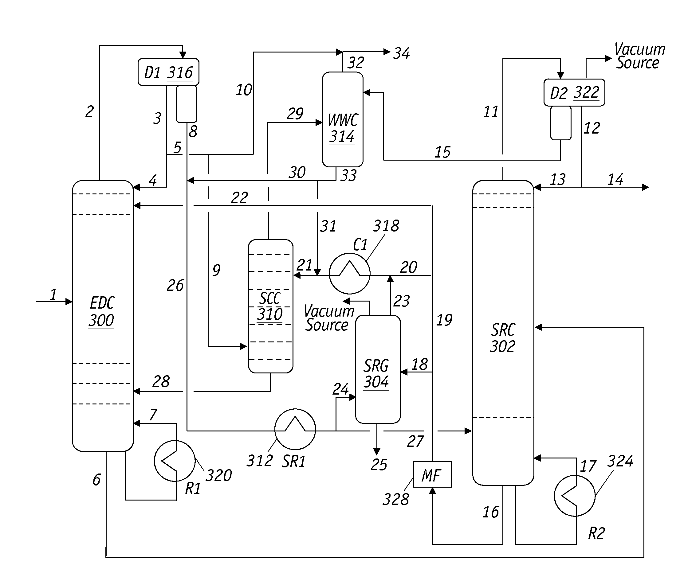
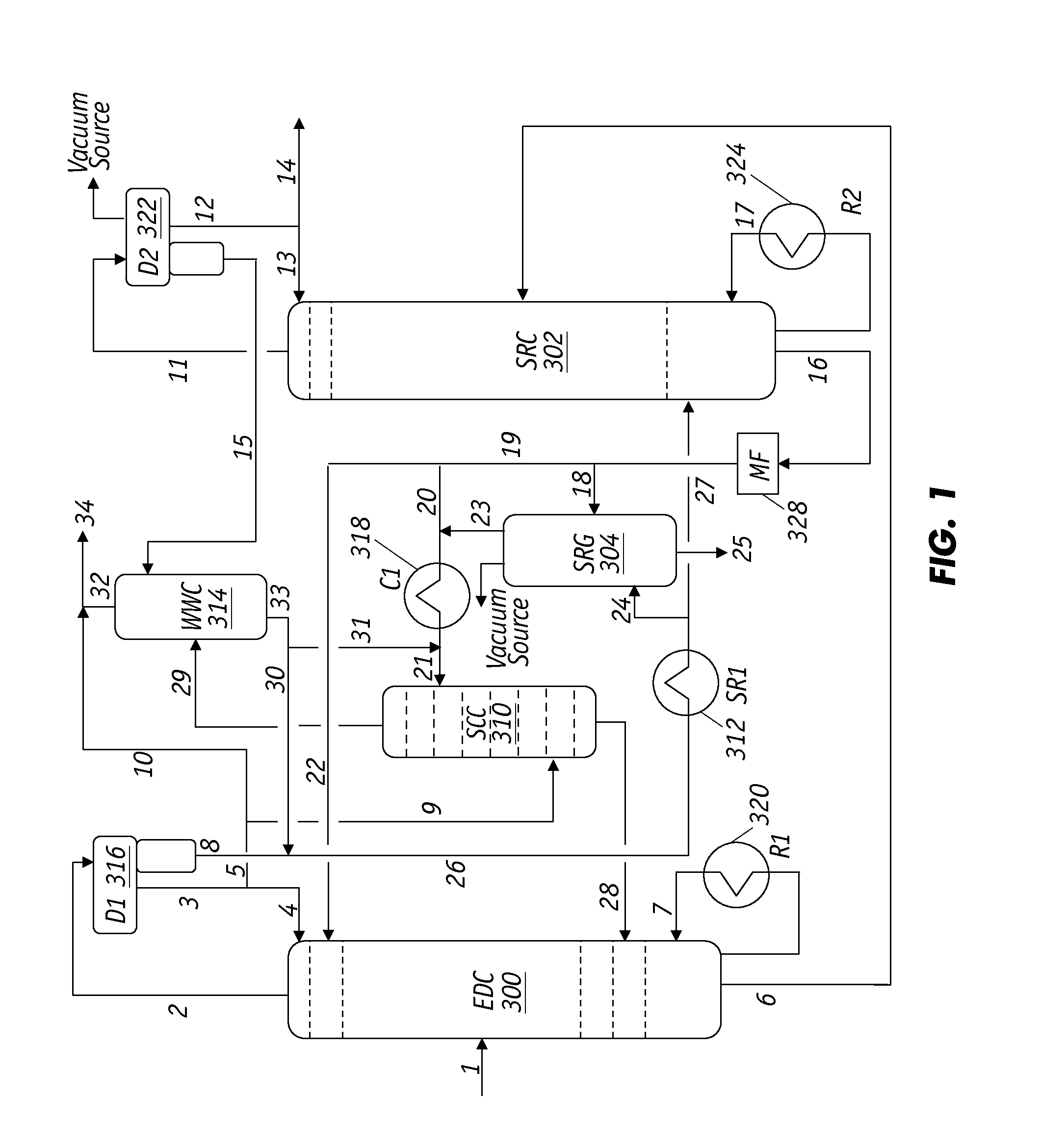
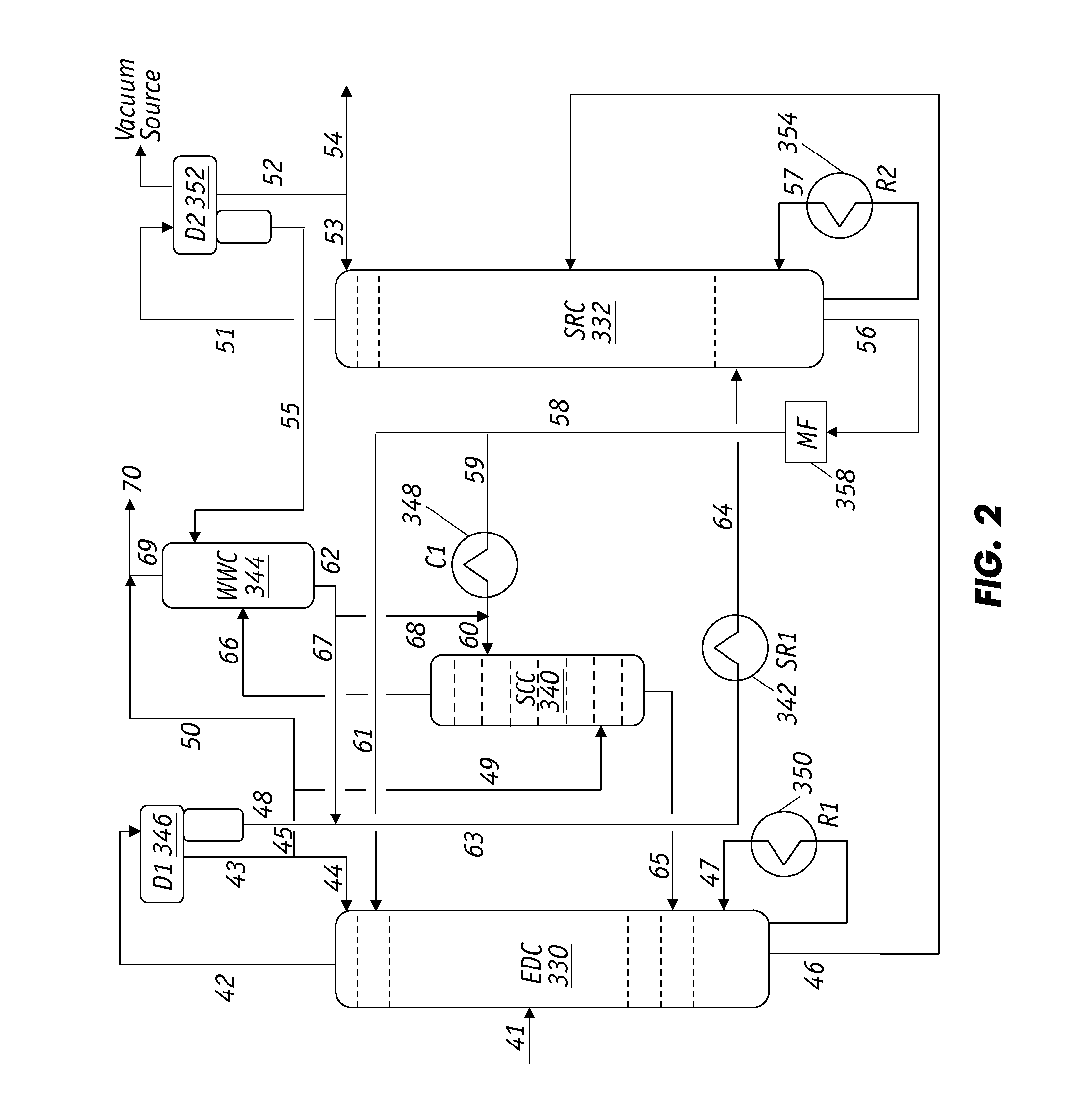
The present invention is about a method for removing heavy HCs and PMs from an extractive solvent. The method involves using a co-displacement agent, which helps to enhance the capability of a displacement agent in removing these contaminants. The method can be incorporated into various processes where a feed mixture containing aromatic and non-aromatic HCs is contacted with a selective solvent. The invention also provides a filter enhanced with a magnetic field for removing para magnetic contaminants in the lean solvent, which helps to minimize the need for a high temperature thermal solvent regenerator.

Problems solved by technology

The solvent regeneration of the Asselin scheme is not suitable for the ED process.
This accumulation is potentially disastrous since the presence of excessive PMs not only changes the solvent properties (selectivity and solvency) significantly but the polymers also plug process equipment to render the ED process inoperable.
Because this water wash method requires much water, it is often difficult to achieve the proper balance and distribution of the process water in the closed system.

Method used


Image

  • Extraction Prcoess with Novel Solvent Regeneration Methods
  • Extraction Prcoess with Novel Solvent Regeneration Methods
  • Extraction Prcoess with Novel Solvent Regeneration Methods

Examples


Embodiment Construction

[0036]The techniques of the present invention can be integration into an ED or LLE process for the selective separation and recovery of polar HCs from a mixture containing the polar and less polar HCs. The inventive processes will be described in relation to the separation and recovery of aromatic HCs from mixtures containing aromatics and non-aromatics, comprising paraffins, isoparaffins, naphthenes, and olefins, but it is understood that the techniques are applicable to a multitude of mixtures. Suitable extractive solvents include, for example, sulfolane, alkyl-sulfolane, N-formyl morpholine, N-methyl pyrrolidone, tetraethylene glycol, triethylene glycol, diethylene glycol, and mixtures thereof, with water as the co-solvent. For aromatic HC recovery, the preferred solvents for the ED process comprise sulfolane with water as the co-solvent and non-aqueous N-formyl morpholine; the preferred solvents for the LLE process comprise sulfolane and tetraethylene glycol and both with water ...


PUM

PropertyMeasurementUnit
boiling pointsaaaaaaaaaa
weight ratioaaaaaaaaaa

Abstract

Solvent regeneration to recover a polar hydrocarbon (HC) selective solvent substantially free of hydrocarbons (HCs) and other impurities from a solvent-rich stream containing selective solvent, heavy HCs, and polymeric materials (PMs) generated from reactions among thermally decomposed or oxidized solvent, heavy HCs, and additives is provided. A combination of displacement agent and associated co-displacement agent squeezes out the heavy HCs and PMs from the extractive solvent within a solvent clean-up zone. Simultaneously, a filter equipped with a magnetic field is positioned in a lean solvent circulation line to remove paramagnetic contaminants. The presence of the co-displacement agent significantly enhances the capability of the displacement agent in removing the heavy HCs and PMs from the extractive solvent. As a result, the solvent regeneration system operates under milder conditions and minimizes or eliminates the need for including a high temperature, energy intensive and difficult-to-operate thermal solvent regenerator.

Description

REFERENCE TO RELATED APPLICATIONS[0001]This application claims priority to U.S. Provisional Patent Application No. 61 / 606,829 which was filed on Mar. 5, 2012.FIELD OF THE INVENTION[0002]The present invention relates generally to removing heavy hydrocarbons and polymeric sludge from a selective solvent after the solvent contacts a feed mixture containing aromatic and non-aromatic hydrocarbons and more particularly to solvent regeneration techniques whereby a co-displacement agent is used to enhance the capability of a primary displacement agent.BACKGROUND OF THE INVENTION[0003]In extractive distillation (ED) and liquid-liquid extraction (LLE) processes for aromatics recovery, the solvent is circulated in a closed loop indefinitely. The feedstock is typically treated in a prefractionator to remove the heavy portion before being fed into the EDC or LLE column. Nevertheless, measurable amounts of heavy hydrocarbons (HCs) pass through even a well-designed prefractionator operating under ...

Claims


Application Information

Patent Timeline
Patent Type & Authority Applications(United States)
IPC IPC(8): B01D3/40
CPCC07C7/08C10G21/12C10G7/08C10G21/28B01D3/40C07C7/10C10G21/20C07C15/02
Inventor LEE, FU-MINGLIN, TZONG-BINWU, KUANG-YEUHWANG, JYH-HAURCHIU, TSUNG-MINLEE, JENG-CHENGJAN, HAN-TJENSUN, YUAN-FU
Owner AMT INT INC
Learn More