
Hybrid Solar Cell Integrating Photovoltaic and Thermoelectric Cell Elements for High Efficiency and Longevity

a solar cell and hybrid technology, applied in the field of solar cells, can solve the problems of reducing the amount of energy which can be generated on a given site, such as a building or a plot of land, adding cost and complexity to the pv system, and disadvantages in cost per unit area, so as to improve the efficiency of array design, prevent the temperature of the cell from reaching a very high, and increase the cell life

Inactive Publication Date: 2013-08-29
UNIV OF CENT FLORIDA RES FOUND INC
View PDF7 Cites 6 Cited by
  • Summary
  • Abstract
  • Description
  • Claims
  • Application Information

AI Technical Summary

Benefits of technology

This patent text describes a hybrid solar cell that uses both heat and a thermoelectric cell to increase efficiency. The cell can operate in two modes: a mode that uses the heat generated from sunlight and other processes to produce electricity, and a mode that uses the thermoelectric cell to cool the photovoltaic cells to increase output in hot conditions. The hybrid cell can also be controlled based on external environmental conditions to optimize its performance. The technical effect of this patent is to improve the efficiency of solar cells in producing electricity.

Problems solved by technology

Large numbers of solar cells require more supporting structure and area with solar access (such as the scarce area on rooftops) adding cost and complexity to PV system, and reducing the amount of energy which can be generated on a given site, such as a building or plot of land.
This incentive for improved power output and area reduction is particularly pressing for crystalline solar cells such as mono-crystalline silicone solar cells, which have higher power output per unit area than thin-film solar cells, but continue to be at a disadvantage in cost per unit area, because of their manufacturing requirements.
Under standard conditions of one sun −1000 W / m2 solar illumination, the typical solar cell operating temperature may increase 30-40° C.—so this negative effect can cause a significant power loss of about 15-20%.
During the winter (in northern climates) the PV panels are exposed to extreme temperature conditions, and potential snow and ice buildup.
A first problem with this configuration is the requirement for a nearby thermal heat requirement, such as heating water.
However, even if such a heat load is present, when the water heater component has stored all the hot water possible, such as during a day when there is no use, the water temperature is so high as to render its cooling effect on the photovoltaic module useless.
Another problem with conventional photovoltaic / thermal is its focus on water heating, which can lead to significant temperature gradients across the array, with corresponding thermal stresses.
Photovoltaic solar cells having a component for reducing heat to increase the output power have been limited to rejection of the photovoltaic heat to domestic or process water heating.
Further problems with this type of cooling include the fact that the cooling effect is often negligible, allowing unacceptable thermal cycling stress on all components and that the thermal load requirements do not allow for optimum design of the electric generation system due to the variability of operating conditions.

Method used


Image

  • Hybrid Solar Cell Integrating Photovoltaic and Thermoelectric Cell Elements for High Efficiency and Longevity
  • Hybrid Solar Cell Integrating Photovoltaic and Thermoelectric Cell Elements for High Efficiency and Longevity
  • Hybrid Solar Cell Integrating Photovoltaic and Thermoelectric Cell Elements for High Efficiency and Longevity

Examples


first embodiment

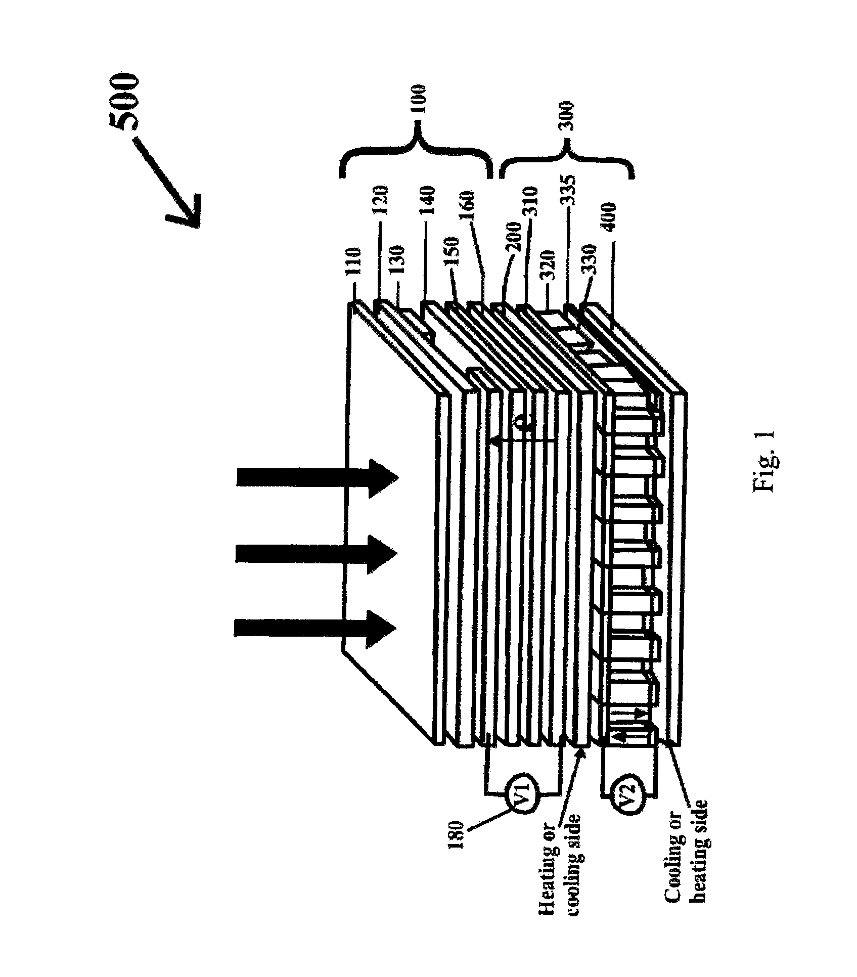
[0041]In summary, a first embodiment provides a method of producing a hybrid solar cell having an increased electric output. The method includes providing photovoltaic cell elements, providing thermoelectric cell elements coupled with the photovoltaic cell elements as a hybrid solar cell and operating the thermoelectric cell elements in an operational mode to efficiently increase the electric output and increase the longevity of the hybrid solar cell.

[0042]The operational modes can include operating the hybrid solar cell in a first mode of operation using heat generated from absorbed solar energy and other heat generating processes, including ohmic heat from current flow through the photovoltaic cell elements and connections with the thermoelectric cell elements configured between this “hot side” and a colder ambient, to produce electric energy and combining the electric output of the thermoelectric cell elements and the photovoltaic cell elements to increase the power output of the...

second embodiment

[0043]A second embodiment provides a hybrid solar cell that includes a photovoltaic cell, a thermoelectric cell coupled with the photovoltaic cell and at least two modes of operation to efficiently increase the electric output and increase the longevity of the hybrid solar cell. The photovoltaic cell includes a first layer for allowing solar light to enter the photovoltaic cell, an anti-reflective layer adjacent to the first layer, a n-type semiconductor layer, a p-type semiconductor layer adjacent to the n-type semiconductor layer, a first conductive layer sandwiched between the anti-reflective layer and one of the n-type and p-type semiconductor elements and a second conductive layer sandwiched between the anti-reflective layer and an opposite one of the n-type and p-type semiconductor elements. The hybrid solar cell can include an electrically insulating layer between the photovoltaic cell and the thermoelectric cell. The thermoelectric cell includes a n-type semiconductor layer,...


PUM


Abstract

Methods, systems and apparatus for a solar cell integrating photovoltaic and thermoelectric cell elements to form a hybrid solar cell having increased efficiency and longevity by combining operation of the photovoltaic and thermoelectric elements in at least three different modes of operation to increase electrical output per unit of panel area and to increase cell life, improve performance, and provide operational benefits under different environmental conditions.

Description

[0001]This application is a divisional application of U.S. patent application Ser. No. 12 / 243,431 filed on Oct. 1, 2008, now U.S. Pat. 8,420,926 issued Apr. 16, 2013, which claims the benefit of priority to U.S. Provisional Application No. 60 / 976,987 filed on Oct. 2, 2007. The entire disclosure of each of the applications listed in this paragraph are incorporated herein by specific reference thereto.FIELD OF THE INVENTION[0002]This invention relates to solar cells and, in particular, to methods, apparatus and systems for a hybrid solar cell integrating photovoltaic and thermoelectric cell elements, wherein the thermoelectric cell element is used to cool and heat the photovoltaic element directly to increase the photovoltaic performance and the thermoelectric cell material is optimized to convert heat dissipated by the photovoltaic element into useful electric energy. Photovoltaic.BACKGROUND AND PRIOR ART[0003]Semiconductor solar cells are utilized to convert light energy to useable ...

Claims


Application Information

Patent Timeline
Patent Type & Authority Applications(United States)
IPC IPC(8): H01L35/28H01L31/024H10N10/10
CPCH01L35/28H01L31/024Y02E10/50H01L31/052H02S10/10H02S40/12Y02B10/10H10N10/10
Inventor REEDY, ROBERT MARTINSORLOAICA-HICKMAN, NICOLETA
Owner UNIV OF CENT FLORIDA RES FOUND INC
Learn More