
Signaling Control Method and System for Service Establishment Based on G.709

a signaling control and service technology, applied in the field of optical network transmission, can solve the problems of interconnection between services, important bearing of 10 gigabit ethernet (loge) on the otn, and the inability to control the signaling control of the service establishment,

Inactive Publication Date: 2013-08-22
ZTE CORP
View PDF11 Cites 3 Cited by
  • Summary
  • Abstract
  • Description
  • Claims
  • Application Information

AI Technical Summary

Benefits of technology

The patent text describes a method and system for controlling signaling in an optical network to connect new devices and old devices, as well as protect network resources. The technical effect is improved efficiency in introducing new services while ensuring the network remains secure and organized.

Problems solved by technology

With the Internet Protocol (IP) normalization for the transport network bearing signals and the popularization of a 10G Local Area Network (LAN) interface, the bearing of 10 Gigabit Ethernet (LOGE) on the OTN becomes an important problem.
When one end-to-end label switching path goes through the old devices and new devices, the related interconnections during the management of end-to-end services become a technical problem existing in the reality.
When the applications of the ODU0 and ODUflex are introduced into the existing network, a problem of interconnection between the networks supporting the 1.25G Timing Sequence (TS) and the deployed networks supporting the 2.5G TS exists.
If no other technologies are introduced, the operators have to upgrade all nodes in the existing network to support the ODU0 and ODUflex, and this certainly will destroy the OTNs which have been invested by the operators.
When one end-to-end ODUk goes through the old devices and new devices, the related interconnections during the management of end-to-end services become a technical problem existing in the reality.
Meanwhile, there also exists the problem of introducing services of the ODU0 and ODUflex into the OTN and interacting with the deployed networks.

Method used


Image

  • Signaling Control Method and System for Service Establishment Based on G.709
  • Signaling Control Method and System for Service Establishment Based on G.709
  • Signaling Control Method and System for Service Establishment Based on G.709

Examples


example 1

[0105]In the example, a specific flow of configuring an end-to-end service when the end-to-end service is established between a node 1 and node 10 in the network shown in FIG. 7 is described, and the following steps are included.

[0106]In step 101, a path computation entity replies routing information, the passed nodes are 1, 3, Gateway 1, 4, 6, 7, Gateway 3, 9 and 10, passed by an end-to-end GigE service to a control plane, and selects the multi stage multiplexing capability ODU0-ODU2-ODU3 on the Gateway 1 and Gateway 3.

[0107]In step 102, the control plane uses a routing result computed by the path computation entity to initiate a signaling process of end-to-end ODU0 connection establishment, and carries the routing information, gateway network elements passed by the routing and the multi stage multiplexing capabilities selected on the gateway network elements in an ODU0 connection establishment signaling. Wherein, an Explicit Region Object (ERO) can be used to carry the routing inf...

example 2

[0113]When a path computation entity receives the following end-to-end service establishment request: an end-to-end ODUflex service between a node 1 and a node 8, the service is marked as an ODUflex 1, and the bandwidth demand is 5*1.25G. The ODUflex 1 service and the GigE 1 service in the example 1 go through the same pair of gateway network elements. In order to fully use bandwidth resources of an ODU3 Network 2, the ODUflex 1 service and the GigE 1 service share a section of ODU2 tunnel, and the available bandwidth satisfies the bandwidth demand of the ODUflex 1. Therefore, after receiving the end-to-end service establishment request, the path computation entity uses the related art to compute an available end-to-end routing, e.g., the passed nodes are 1, 3, Gateway 1, 4, 6, 7, Gateway 3 and 8. Since the Gateway 1 and Gateway 3 only support the two level multiplexing capability and demultiplexing capability of the ODUflex-ODU2-ODU3 with respect to an ODUflex service, the path com...

example 3

[0122]In the present invention, it is required to carry multi stage multiplexing capability information selected by a path computation entity for the passed gateway network elements in a signaling message (Path or Resv).

[0123]A method for carrying the multi stage multiplexing capability information is: in an Explicit Route Object (ERO) or an Explicit Route Boundary Object (ERBO), embedding the multi stage multiplexing capability information used on the gateway network elements and selected by the path computation entity in a subject of the ERO or ERBO of marking the gateway network element.

[0124]A specific embodiment of embedding the multi stage multiplexing capability in the subject is: in the subject of the ERO or ERBO marking the gateway network element, inserting attribute information following behind the subject of a node identifier or an interface index identifier, such as HOP_ATTRIBUTES, wherein the HOP_ATTRIBUTES contain a multi stage multiplexing method selected by the path...


PUM


Abstract

A signaling control method for service establishment based on G.709 is provided in the present invention, including: a control plane obtaining routing information of an end-to-end service to be established, information of a gateway network element passed by end-to-end service routing and a multi stage multiplexing capability selected for the gateway network element, initiating an end-to-end connection establishment process, and sending an end-to-end connection establishment signaling to nodes passed by the end-to-end service routing, wherein, the end-to-end connection establishment signaling contains the multi stage multiplexing capability selected for the gateway network element passed by the end-to-end service routing, and a corresponding multi stage multiplexing capability is configured on the gateway network element. A signaling control system for service establishment based on G.709 is also provided in the present invention. In the method and system, the interconnection between old devices and new devices is better implemented.

Description

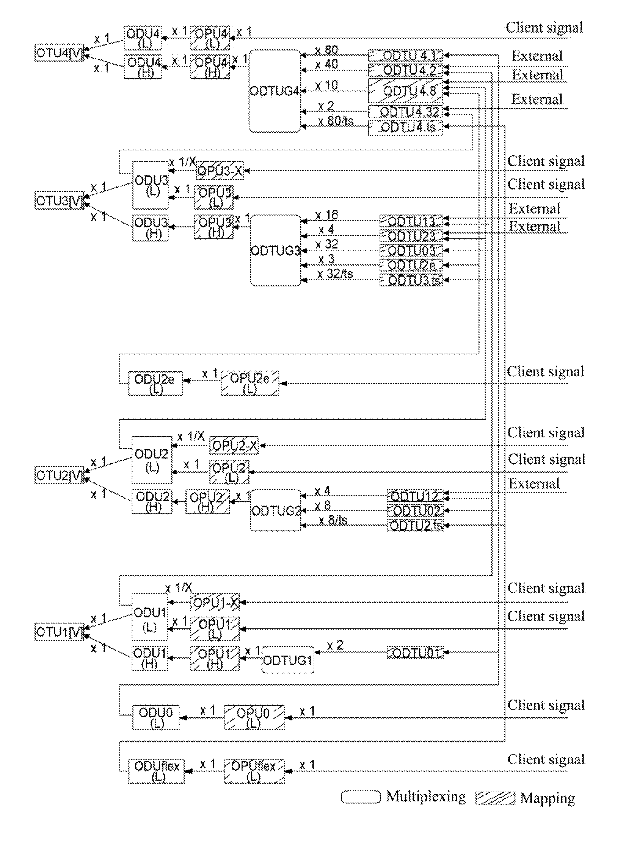
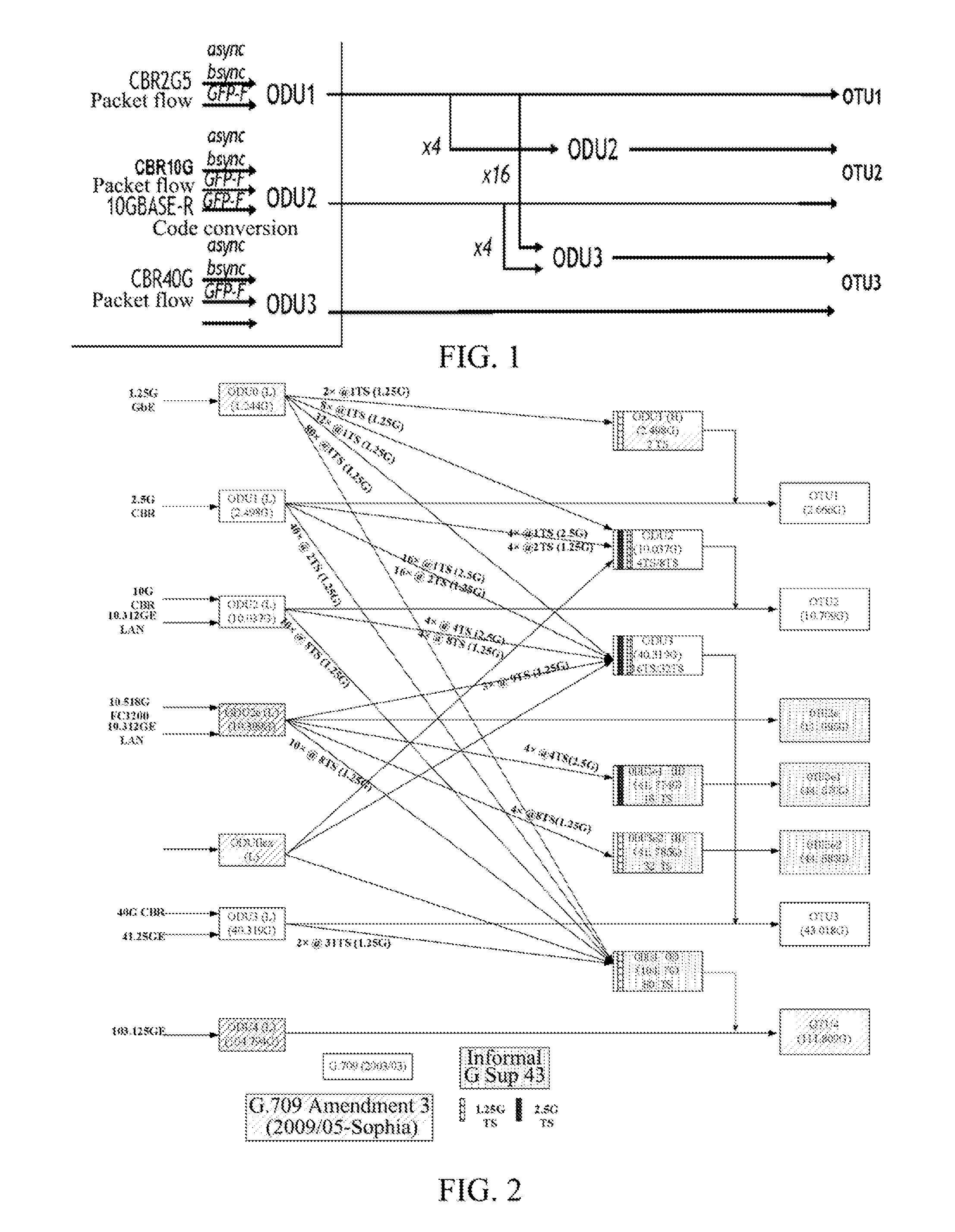
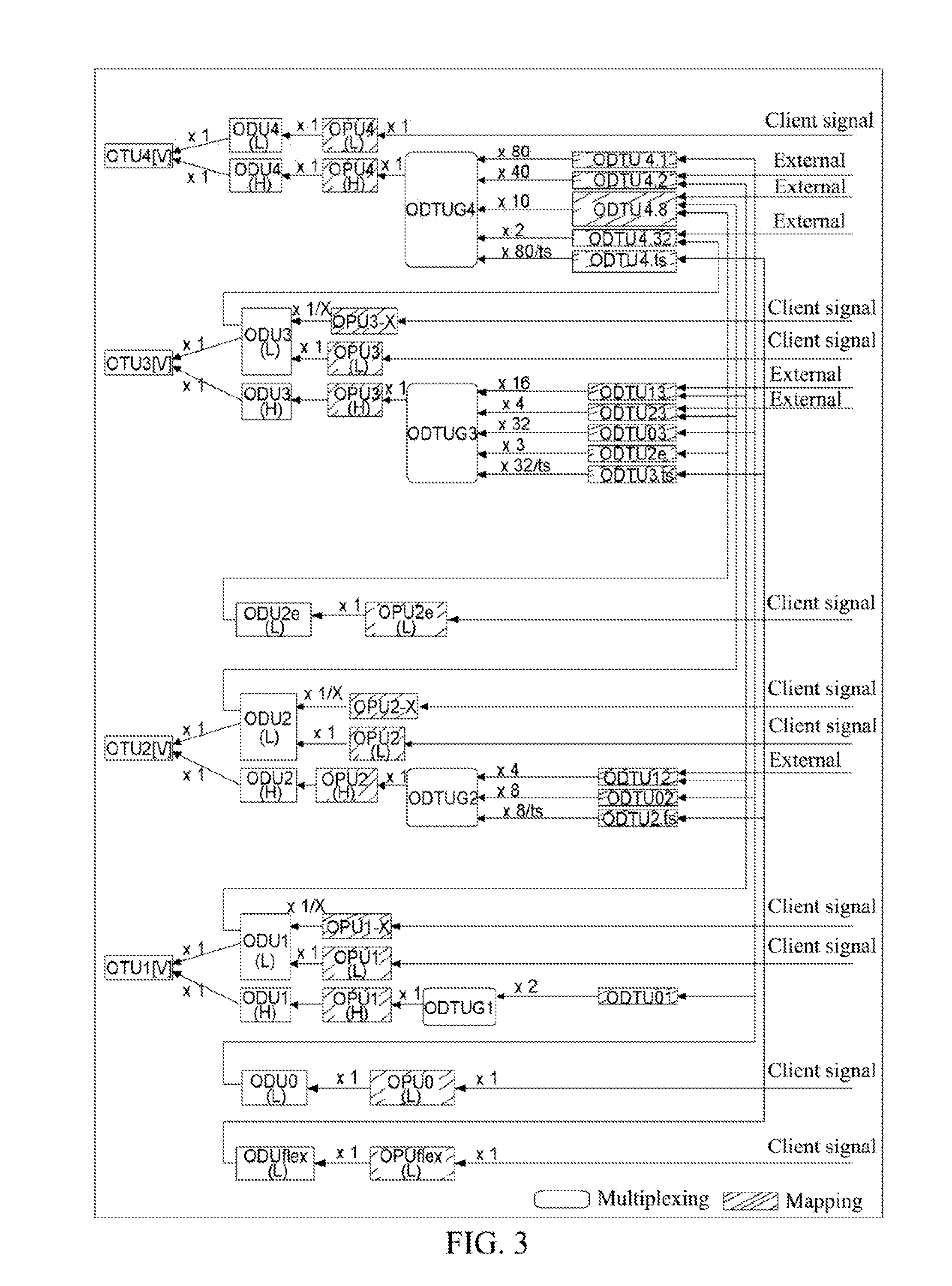
TECHNICAL FIELD[0001]The present invention belongs to the field of optical network transmission, and particularly, to a method and system for signaling control for service establishment based on G.709 in an automatic switching optical network of optical transport network.BACKGROUND OF THE RELATED ART[0002]The Optical Transport Network (OTN) is a technique of digital wrapper disclosed in 1999 to solve the problem of high capacity transmission for high speed Time Division Multiplexing (TDM) signals. The OTN defined in the version of 2003 can provide functions such as transmission, multiplexing, protection and monitoring management and so on for client layer signals, where the supported client layer signals are mainly Ethernet signals supported by the Synchronous Transmission Mode Level N (STM-N) and Asynchronous Transmission Mode (ATM) and supported through the Generic Framing Procedure (GFP), and the defined rate levels are 2.5G, 10G and 40G. With the Internet Protocol (IP) normaliza...

Claims


Application Information

Patent Timeline
Patent Type & Authority Applications(United States)
IPC IPC(8): H04Q11/00
CPCH04J3/1652H04J2203/006H04J2203/0089H04Q11/0062H04Q2011/0064H04Q2011/0073H04Q2011/0088H04J3/12H04J2203/0057H04J2203/0085H04B10/27H04Q11/00
Inventor FU, XIHUAZHANG, XINLING
Owner ZTE CORP
Learn More