Hybrid sequential and simultaneous process simulation system

a process simulation and simultaneous technology, applied in process control, process and machine control, instruments, etc., can solve the problems of inability to meet real-time simulation applications, and inability to achieve real-time simulation applications. achieve the effect of stable numerical results and fast execution speed

Active Publication Date: 2013-08-15
EMERSON PROCESS MANAGEMENT POWER & WATER SOLUTIONS
View PDF57 Cites 21 Cited by
  • Summary
  • Abstract
  • Description
  • Claims
  • Application Information

AI Technical Summary

Benefits of technology

[0014]Importantly, this hybrid pressure / flow calculation technique provides for fast execution speeds during each simulation cycle because the set of simultaneous equations being solved is greatly reduced in size and complexity as compared to typical simulation systems that simultaneously solve all of the process nodes together, making this technique suitable for real-time simulation applications. Moreover, because the process element flow conductances are determined anew in any particular simulation cycle based on the actual state of the process elements (and thus are dynamically determined in real-time), and because all upstream and downstream simulation modules are known to each other via a chained system ID, this technique is able to re-construct systems of equations during run-time more effectively, and thus avoids the occurrence of matrix singularities within the set of simultaneously solved pressure and flow equations, leading to stable numerical results in the process network simulation system even when various nodes of the process network are isolated from the rest of the network due to current process network settings or conditions.

Problems solved by technology

None-the-less, only the most complex simulation systems are typically able to perform high fidelity simulation of a process plant because of the complex processes being implemented, the ever changing conditions within the plant including the degradation of devices over time and the presence of unaccounted for disturbance variables within the plant.
However, the pressure and flow propagation speed through the network is slow, and if not handled appropriately, the flow imbalances can result in a poor degree of simulation fidelity.
However, this technique has the disadvantage that it can take a long time and / or a great deal of processing power to find a solution during each time interval or simulation cycle.
This fact makes this technique sometimes impractical for real-time simulation applications, especially in large process networks having a lot of process nodes.
Another shortcoming of this approach is that the entire equation structure is prebuilt or pre-established, and the centralized solver may therefore experience difficulty in handling matrix singularities that can arise in certain situations.
For example, when two valves in the same straight flow path are both closed, the solver may not be able to determine the pressures in between these valves, if the equations are not processed properly.
However, a major drawback associated with this type of simulation system is that the physical models are complex and computationally expensive, especially when the system to be modeled is highly nonlinear and interactive.
As a result, these types of simulation systems are usually slow, computationally inefficient, and may be numerically unreliable in certain process situations.
However, efficient solving of the pressure-flow variables at each of the process nodes by the distributed simulated network is an important part of real-time process simulation, as without it, the simulation will not be very accurate or useful.
Because all of the process components being simulated are connected together in a network, the time required to complete the entire set of calculations can be challenging, especially when the network size is large, due at least in part to the slow propagation of pressure and flow calculations between the various different simulation modules within the distributed simulation system.

Method used


Image

  • Hybrid sequential and simultaneous process simulation system
  • Hybrid sequential and simultaneous process simulation system
  • Hybrid sequential and simultaneous process simulation system

Examples


Embodiment Construction

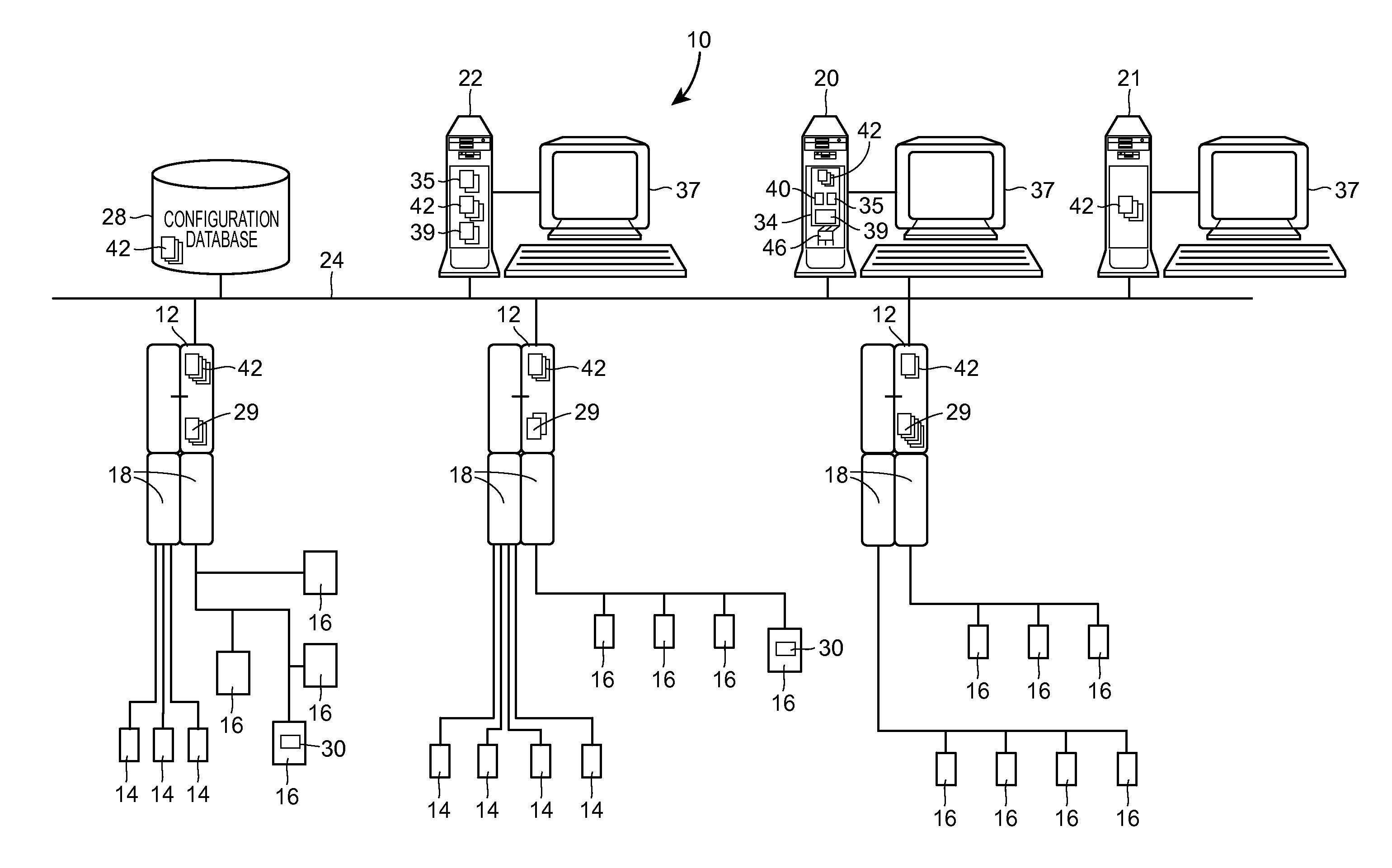
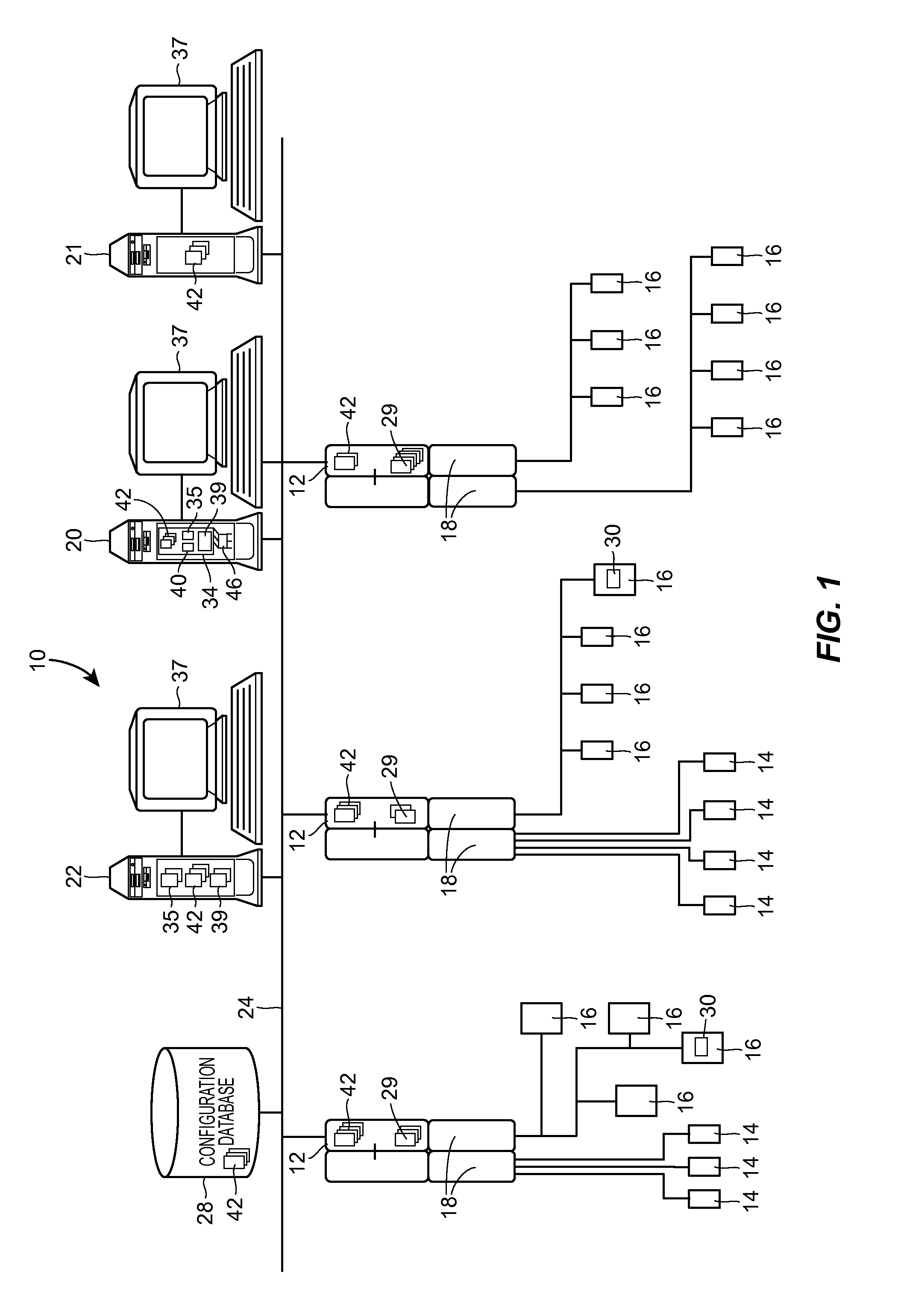
[0021]Referring now to FIG. 1, an example distributed control network for a plant 10, such as that associated with a power generation plant, an industrial manufacturing plant, a processing plant, etc., is illustrated at an abstract level of detail. The plant 10 includes a distributed control system having one or more controllers 12, each of which is connected to one or more field devices 14 and 16 via input / output (I / O) devices or cards 18 which may be, for example, Fieldbus interfaces, Profibus® interfaces, HART® interfaces, standard 4-20 ma interfaces, etc. The controllers 12 are also coupled to one or more host or operator workstations 20, 21 and 22 via a data highway 24 which may be, for example, an Ethernet link. A database 28 may be connected to the data highway 24 and operates as a data historian to collect and store parameter, status and other data associated with the controllers 12 and field devices 14, 16 within the plant 10. Additionally or alternatively, the database 28 ...


PUM


Abstract

A pressure and flow calculation technique that efficiently solves for pressures and flows within a process network uses both a simultaneous and a sequential solving method. The calculation technique first determines a flow conductance for each of the process network elements, linearizes pressure and flow relationships in each flow path by determining a linearized flow conductance for each process element and then determines a composite process network having a linearized, composite process component in each flow path to produce a simplified process network. A simultaneous solving method is then used to simultaneously solve for the pressures and flows at each of a set of junction nodes of the simplified process network and thereafter a sequential solving method is applied to determine the pressures and flows at the other nodes of the process network.

Description

TECHNICAL FIELD[0001]The present invention relates generally to simulating the operation of flow networks such as those used in power generation plants, industrial manufacturing plants, processing plants and other types of process plants and, more particularly, to a system and method for efficiently solving pressure / flow parameters in real-time in a process network simulation system.DESCRIPTION OF THE RELATED ART[0002]Distributed process control systems, like those typically used in power generation, chemical manufacturing, petroleum processing, industrial manufacturing or other types of plants, typically include one or more controllers communicatively coupled to a plurality of field devices via analog, digital, combined analog / digital, or wireless buses. The field devices, which may be, for example, valves, valve positioners, switches, transmitters (e.g., temperature, pressure, level and flow rate sensors), burners, heat exchangers, furnaces, etc. are located within the plant envir...

Claims


Application Information

Patent Timeline
Patent Type & Authority Applications(United States)
IPC IPC(8): G05D7/00
CPCG06F17/5018G05B17/02G06F30/23G05B17/00G05B19/41885
Inventor CHENG, XUBUSH, KIRT T.
Owner EMERSON PROCESS MANAGEMENT POWER & WATER SOLUTIONS
Why Eureka
Try Eureka