
Method and Device for Air Conditioning with Humidity Control

a technology of air conditioning and humidity control, which is applied in the direction of domestic cooling apparatus, heating types, separation processes, etc., can solve the problems of inefficiency of process, add to the maintenance cost of air conditioning systems, and conventional air conditioning systems generally do not perform humidity control functions, etc., to achieve the effect of improving the air temperature and humidity control devi

Inactive Publication Date: 2013-08-08
CARRIER CORP
View PDF6 Cites 62 Cited by
  • Summary
  • Abstract
  • Description
  • Claims
  • Application Information

AI Technical Summary

Benefits of technology

The present invention is an improved air temperature and humidity control device. It includes a heat pump, humidity controller, and blower. The heat pump circulates a refrigerant and the humidity controller contains a contactor and a liquid desiccant. The device has a contactor with a porous sidewall that helps to control air temperature and humidity by generating airflow along its exterior side. The technical effects of this invention are improved precision in controlling air temperature and humidity, as well as improved efficiency in energy usage. The method of controlling air humidity and temperature involves circulating both the refrigerant and the liquid desiccant in the device. The device can be modified for different applications without much experimentation.

Problems solved by technology

Conventional air conditioning systems generally do not perform humidity control functions.
Significant energy is consumed during the supercooling and reheating, which renders the process inefficient.
Moreover, water condensation on metallic DX coils may cause corrosion problems, which adds to the maintenance cost of the air conditioning systems.
While capable of achieving low humidity outputs, systems based on desiccant wheels may be space-consuming and may suffer from lack of efficiency, as heating energy is required to regenerate the desiccant.
Moreover, because the desiccant wheel is relatively cumbersome and not easy to install or uninstall, the capacity and operation of the systems based on desiccant wheels are generally not modular enough to accommodate a wide range of operations.
However, as the operation of the system requires direct contact between numerous streams of liquid desiccant and air, significantamount of noises, e.g. bubbling noise, are generated by the system, which may disturb the ambience of the room or facility that is the subject of the system.
Such liquid desiccant entrainment (or liquid desiccant carryover) can cause corrosion of ductwork and human health issues.
Moreover, similar to the desiccant wheels, the contact towers of the above-discussed system is relatively cumbersome in construction and not easy to modulate to accommodate a wide range of operations.

Method used


Image

  • Method and Device for Air Conditioning with Humidity Control
  • Method and Device for Air Conditioning with Humidity Control
  • Method and Device for Air Conditioning with Humidity Control

Examples


first embodiment

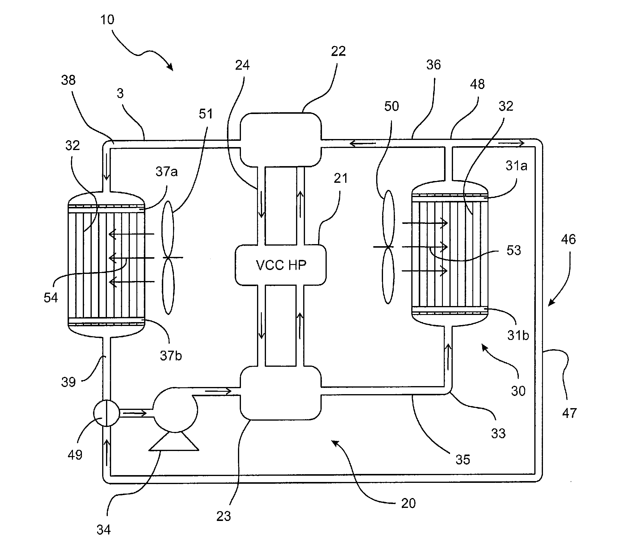
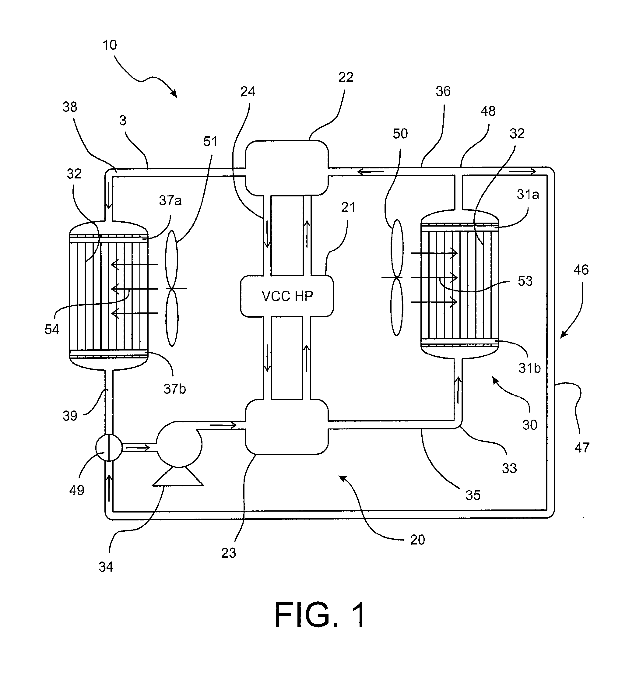
[0021]This disclosure is generally related to an improved air temperature and humidity control device. In a first embodiment schematically illustrated in FIG. 1, the device 10 may include a heat pump 20, a humidity controller 30, and a blower 50. The heat pump 20 may include a compressor 21, an evaporator 22, and a condenser 23. In operation, a refrigerant 24 may be circulated in the heat pump 20 among the evaporator 22, condenser 23, and compressor 21 so that the refrigerant 24 is in a compressed state (heat releasing) in the condenser 23 and is in an expanded state (heat absorbing) in the evaporator 22. As a non-limiting example, the refrigerant may be an environmentally friendly refrigerant based on R-410. Other suitable refrigerants may also be used by one of ordinary skill in the art in view of this disclosure without undue experimentation.

[0022]The humidity controller 30 may include a first contactor 31 and a liquid desiccant 33 flowing therethrough. The heat pump 20 and humid...

second embodiment

[0026]In the second embodiment, a second blower 51 may be provided to generate airflow 54 over the second contactor 37. Similar to the first blower 50, the second blower 51 may include an electric fan positioned adjacent to the second contactor 37. In another embodiment, the electric fan may be substituted by an air outlet of an HVAC system. As the airflow 54 passes over the second contactor 37, heat and / or water transfers between the airflow 54 and liquid desiccant 33 in the second contactor 37 allow the disclosed device 10 to provide desirable air temperature and / or humidity.

[0027]To facilitate the thermal coupling between the heat pump 20 and humidity controller 30, the evaporator 22 and the condenser 23 may be both refrigerant-desiccant heat exchangers, rather than refrigerant-air heat exchangers used in conventional air conditioning systems. As a result, no direct expansion (DX) coil is used in the disclosed device. As a non-limiting example, the refrigerant-desiccant heat exch...


PUM


Abstract

An air temperature and humidity control device using a liquid-desiccant humidity controller thermally coupled to a heat pump is disclosed. The humidity controller may include a contactor having at least one contact module with a porous sidewall that is permeable to water vapor and impermeable to the liquid desiccant. The disclosed device provides air temperature control through heat transfer between the liquid desiccant and heat pump and provides humidity controls through water transfer between the desiccant and surrounding air.

Description

CROSS-REFERENCE TO RELATED APPLICATION[0001]This application is a non-provisional patent application claiming priority under 35 USC §119(e) to U.S. Provisional Patent Application Ser. No. 61 / 263,687 filed on Nov. 23, 2009.BACKGROUND[0002]1. Technical Field[0003]An air temperature and humidity control device using a liquid-desiccant humidity controller thermally coupled to a heat pump is disclosed. The humidity controller includes a contactor having at least one contact module with a porous sidewall that is permeable to water vapor and impermeable to the liquid desiccant. The disclosed device controls air temperature through heat transfer between the liquid desiccant and heat pump and controls humidity through water transfer between the desiccant and surrounding air.[0004]2. Description of the Related Art[0005]Conventional air conditioning systems generally do not perform humidity control functions. In case humidity control is desired, air conditioners based on direct expansion (DX) ...

Claims


Application Information

Patent Timeline
Patent Type & Authority Applications(United States)
IPC IPC(8): F24F6/12F24F11/00F24F6/00
CPCB01D53/263F24F3/1417F24F11/0008F24F6/00F24F6/12F24F2003/1435
Inventor MA, ZIDUJIANG, YIRONGLUO, DONG
Owner CARRIER CORP
Learn More