
Target device, sputtering apparatus and method for manufacturing a target device

a target device and sputtering technology, applied in the direction of manufacturing tools, non-electric welding apparatus, solventing apparatus, etc., can solve the problems of troublesome removal, large amount of gas discharge, protruding brazing material adhesion to the backing plate, etc., and achieve the effect of low adhesion of an iridium brazing material

Active Publication Date: 2013-07-25
ULVAC INC
View PDF10 Cites 5 Cited by
  • Summary
  • Abstract
  • Description
  • Claims
  • Application Information

AI Technical Summary

Benefits of technology

The invention aims to solve the issues of conventional protective films by providing a protective film that releases minimal gas and has excellent protective properties.

Problems solved by technology

Although a conventional protective thin film exhibiting higher surface smoothness than a sprayed thin film has been obtained, such a thin film cannot sufficiently protect the backing plate and a large amount of gas is discharged.
Furthermore, when attaching the target plate to the backing plate with a brazing material, there has been a problem in that protruding brazing material adheres to the backing plate and is troublesome to remove.

Method used


Image

  • Target device, sputtering apparatus and method for manufacturing a target device
  • Target device, sputtering apparatus and method for manufacturing a target device
  • Target device, sputtering apparatus and method for manufacturing a target device

Examples


Embodiment Construction

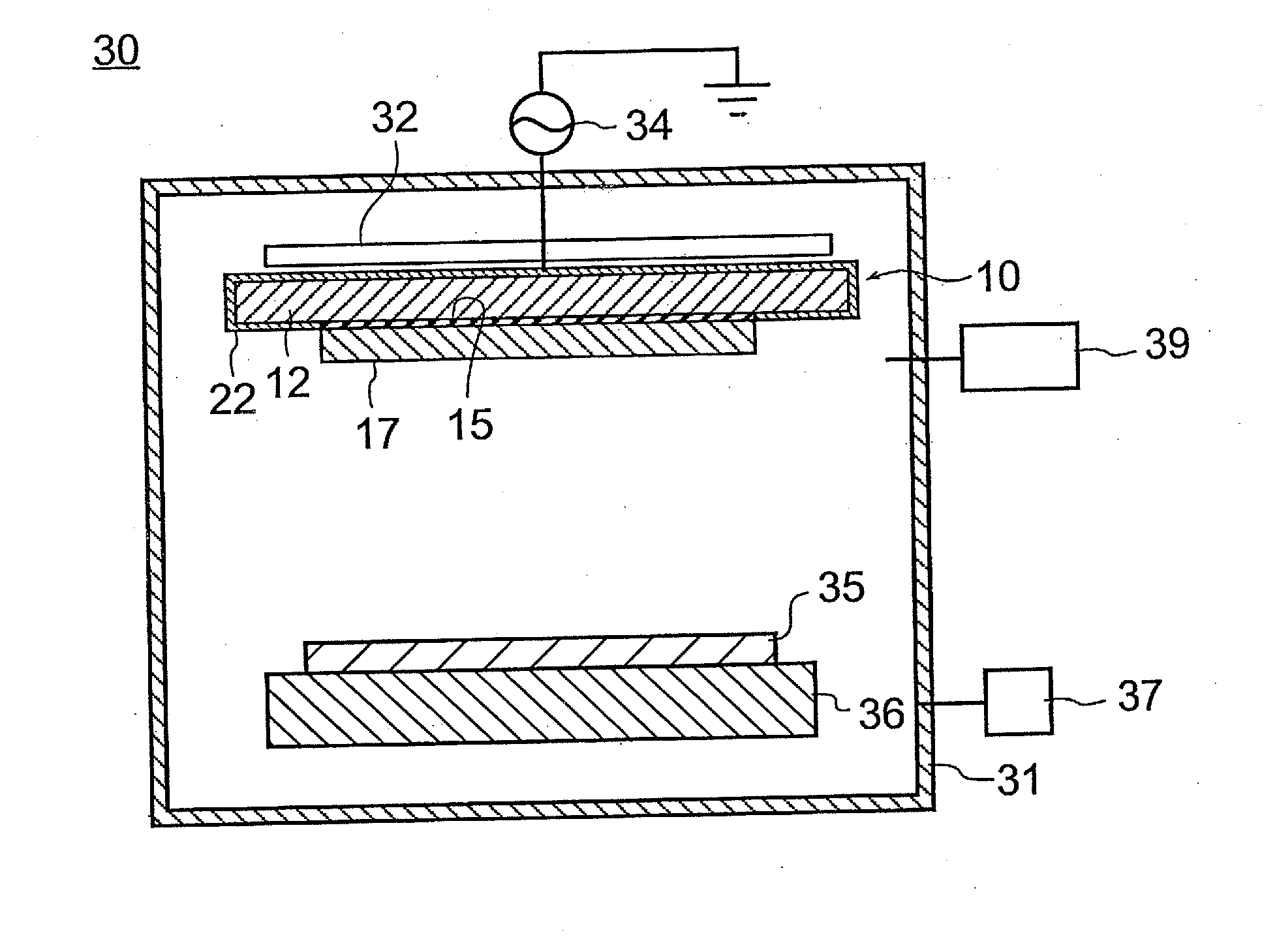
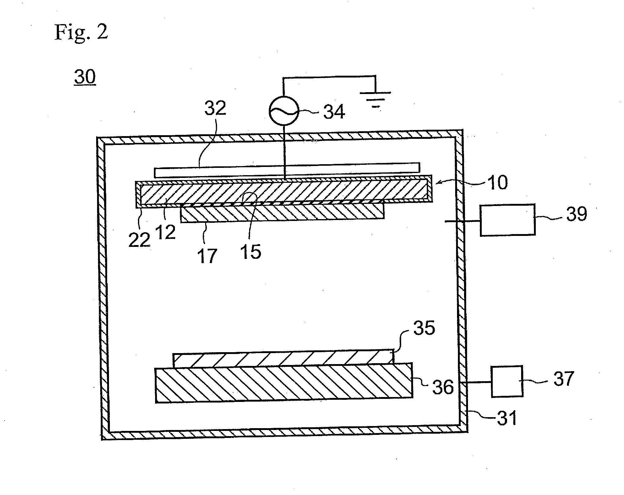
[0025]FIG. 2 shows a sputtering apparatus 30 having a vacuum chamber 31. A target device 10 of the present invention is disposed inside the vacuum chamber 31.

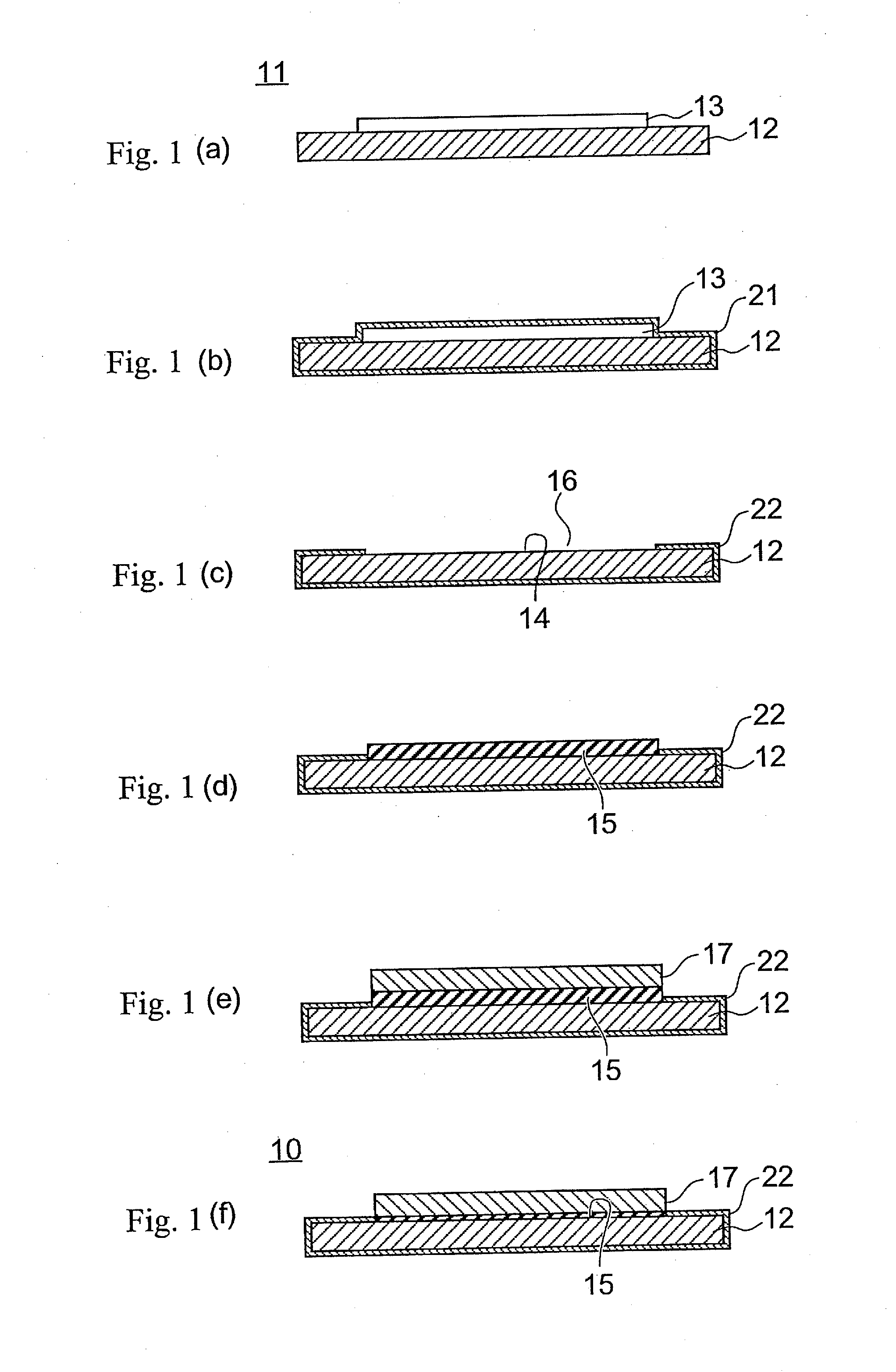
[0026]As shown in FIG. 1(f), the target device 10 has a metallic backing plate 12. A target plate 17 is attached onto the backing plate 12 by a metal brazing material 15. In this example, the backing plate 12 is made of pure copper or a copper alloy, and the metal brazing material 15 is made of iridium including additives.

[0027]A substrate holder 36 is provided at a position facing the target plate 17 in the vacuum chamber 31. A substrate 35 is disposed on the substrate holder 36.

[0028]The inside of the vacuum chamber 31 is evacuated in advance by a vacuum pump system 37. A sputtering gas is then introduced into the vacuum chamber 31 from a gas introduction system 39. When a voltage is applied to the target device 10 by a sputtering power source 34, the surface of the target plate 17 is sputtered and a thin film is formed on th...


PUM

PropertyMeasurementUnit
Pressureaaaaaaaaaa
Electric potential / voltageaaaaaaaaaa

Abstract

To provide a target device that can easily be reused in which the amount of gas discharge is small. The present invention is a target device including a backing plate and a target plate that is fixed to the backing plate with a metal brazing material, in which a protective film made of a TiN thin film in which a proportion of (111) plane is at a maximum is formed on an exposed portion of the backing plate. The discharge amount of gas is small, and the brazing material that adheres when fixing the target plate can be easily peeled off.

Description

BACKGROUND[0001]The present invention is generally related to a target device provided with a protective film and a sputtering apparatus including the target device, and more particularly to a target device provided with a protective film that protects a backing plate and a sputtering apparatus including the target device.[0002]Currently, thin films (such as, electrodes in a semiconductor apparatus or flat display apparatus) are made using a sputtering apparatus. In a sputtering apparatus, a target device having a target plate formed from constituent materials of a thin film is disposed inside a vacuum chamber and plasma is formed inside the vacuum chamber. The ions inside the plasma are accelerated and impact the target plate so that the target plate is sputtered, and thereby a thin film is formed on a surface of a substrate.[0003]A negative voltage is generally applied to the target plate; and thus, the target plate is attached to a metal backing plate that serves as a cathode ele...

Claims


Application Information

Patent Timeline
IPC IPC(8): C23C14/34
CPCC23C14/3407C23C14/32C23C14/0641B23K1/0008
Inventor KADOWAKI, YUTAKATAKAHASHI, KAZUTOSHISATO, MASARULIN, CHENGFU
Owner ULVAC INC
Learn More