Word line and power conductor within a metal layer of a memory cell

Active Publication Date: 2013-07-18
ARM LTD
View PDF1 Cites 6 Cited by
  • Summary
  • Abstract
  • Description
  • Claims
  • Application Information

AI Technical Summary

Benefits of technology

The present technique aims to improve the performance of memory cells in integrated circuits. It does this by using word lines in the M3 or higher metal layers and reducing the capacitive coupling between them. By depopulating power conductors within the word line layer and widening areas of interstitial gaps, the resistance of the word lines is reduced, which increases the speed of operation and reduces power consumption. Additionally, the technique reduces routing congestion by using the third metal layer for the word line layer. The memory cells also comprise separate power line sections that are staggered on each side of a word line to further reduce resistance. The memory cell design facilitates the use of vias in an interleaved arrangement to avoid processing geometry constraints.

Problems solved by technology

Furthermore, the interstitial gaps between the separate power line sections permit the word lines to be widened in areas adjacent those interstitial gaps thereby reducing the resistance of the word lines.

Method used


Image

  • Word line and power conductor within a metal layer of a memory cell
  • Word line and power conductor within a metal layer of a memory cell
  • Word line and power conductor within a metal layer of a memory cell

Examples


Embodiment Construction

[0035]FIG. 1 illustrates an integrated circuit 2 including an array of memory cells 4. Each memory cell 6 within a row of memory cells is connected to a word line WL running across the array. Bit lines

[0036]BL running perpendicular to the word lines WL are used to read bit values from the memory cells 6 and write values to the memory cells 6. It will be appreciated that in practice, the array 4 is a two-dimensional array that may contain a large number of memory cells necessary to provide a memory of high capacity.

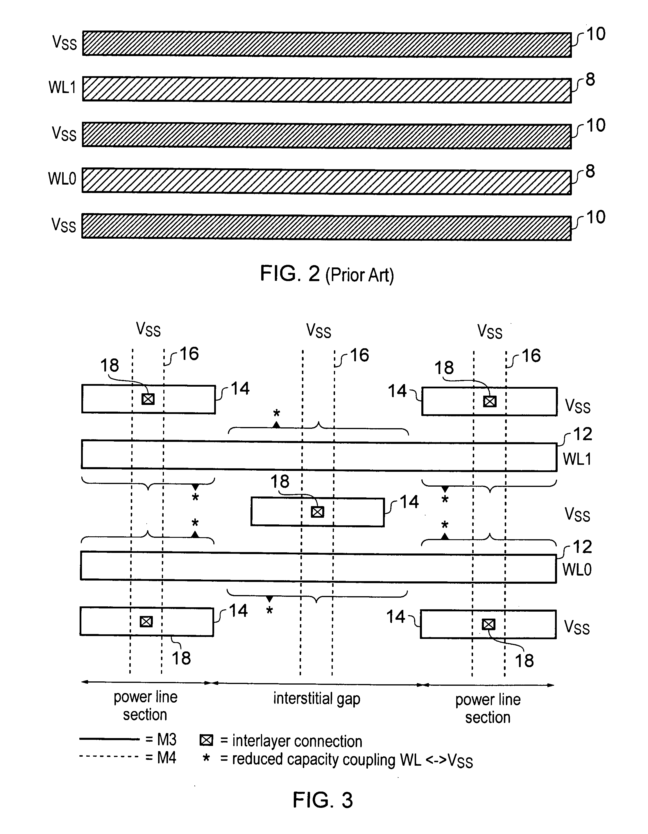
[0037]FIG. 2 illustrates a possible prior art metal layer within the memory cells 6. This metal layer includes continuous word lines 8 running across the memory cells and continuous power conductors 10 parallel to the word lines 8 and also running across the memory cells. A problem with this approach is the relatively high capacitative coupling between the word lines 8 and the power conductors 10 which results in a high RC value for the word lines and slow operation of the...


PUM


Abstract

A memory cell 6 includes a M3 metal layer which incorporate continuous word lines 12 and power conductors formed of a plurality of separate power line sections 14 running parallel to the word lines. Interstitial gaps between the separate power line sections are larger in size than the power line sections themselves. The power line sections are disposed in a staggered arrangement either side of the word lines.

Description

BACKGROUND OF THE INVENTION[0001]1. Field of the Invention[0002]This invention relates to the field of memory cell layouts. More particularly, this invention relates to the layout of word lines and power conductors within a metal layer of a memory cell.[0003]2. Description of the Prior Art[0004]It is known to provide memory cells which include multiple metal layers. As process geometries shrink, such as to 20 nm, various problems arise that were not encountered in larger process geometries. One example is the constraint upon minimum via spacing. One way of addressing this is to move the word lines into the M1 or M2 layers. However, a problem with this approach is that it results in a larger RC value associated with the word lines and this slows down memory accesses and memory cycle times. Furthermore, the increase in the RC of the memory line will also increase the power consumed and the area of the memory if it is necessary to buffer the word line.SUMMARY OF THE INVENTION[0005]View...

Claims


Application Information

Patent Timeline
IPC IPC(8): G11C5/06H01L21/768
CPCG11C5/063G11C8/14H01L27/10891H01L27/1052H01L27/0207H10B99/00H10B12/488H01L27/10
Inventor CHONG, YEW KEONGYEUNG, GUS
Owner ARM LTD
Why Eureka
Try Eureka