
Adiabatic rapid passage atomic beamsplitter using frequency-swept coherent laser beam pairs

Active Publication Date: 2013-07-04
CHARLES STARK DRAPER LABORATORY
View PDF4 Cites 10 Cited by
  • Summary
  • Abstract
  • Description
  • Claims
  • Application Information

AI Technical Summary

Benefits of technology

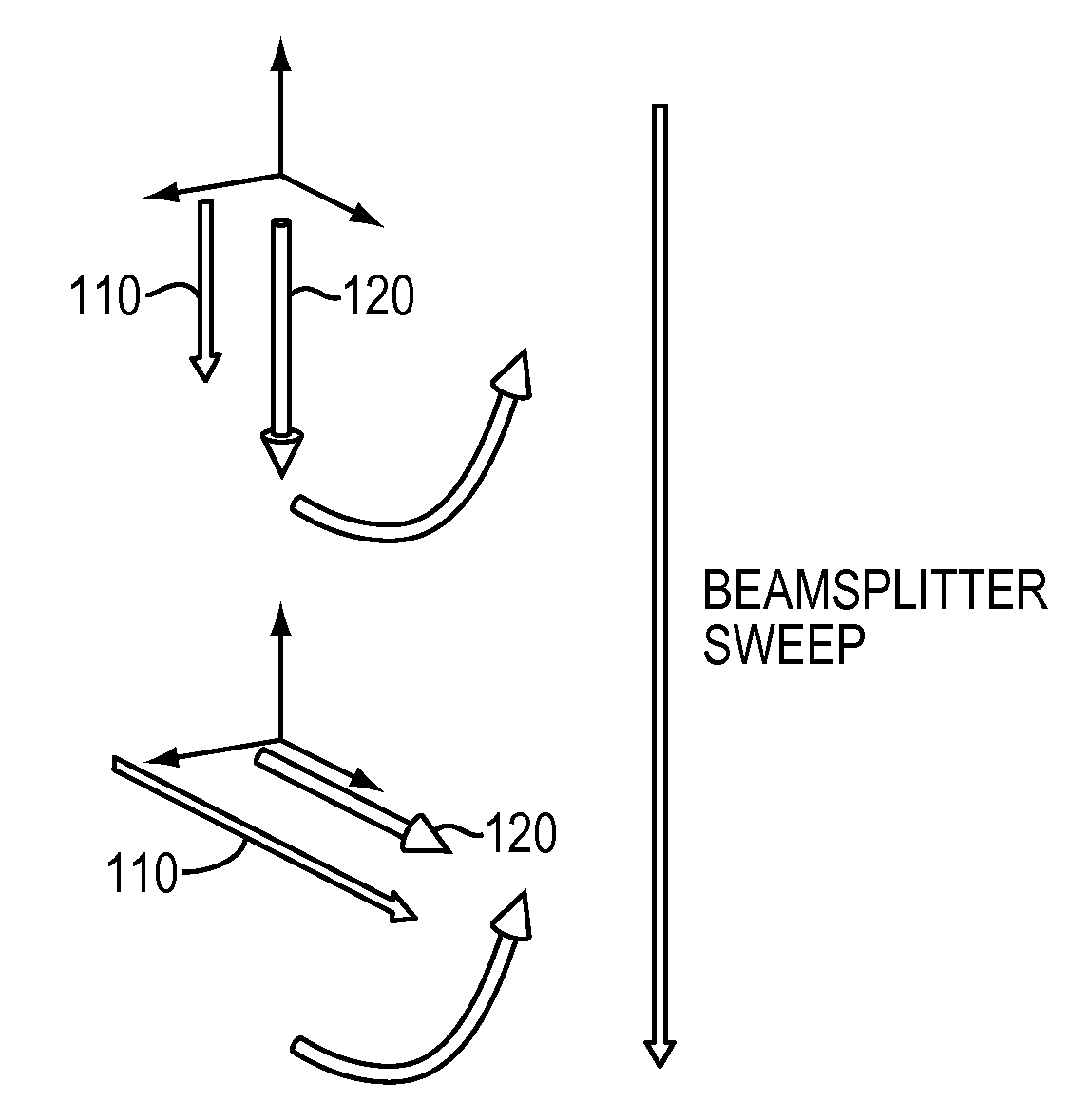
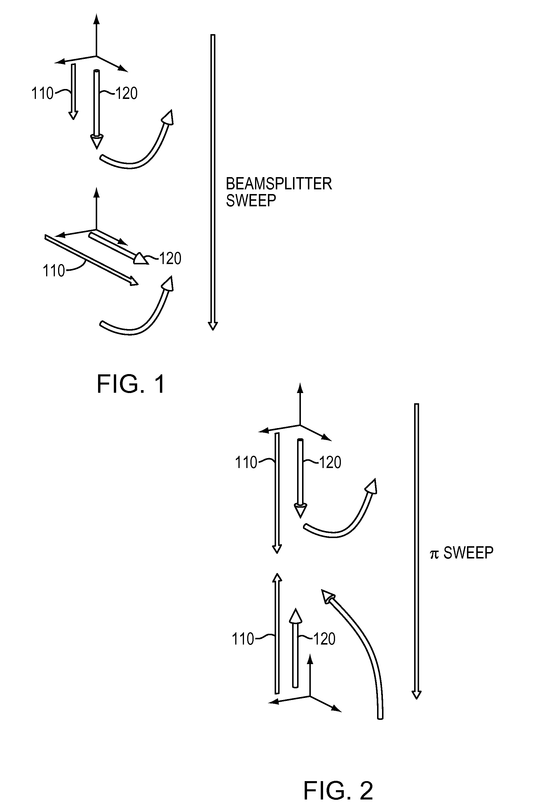
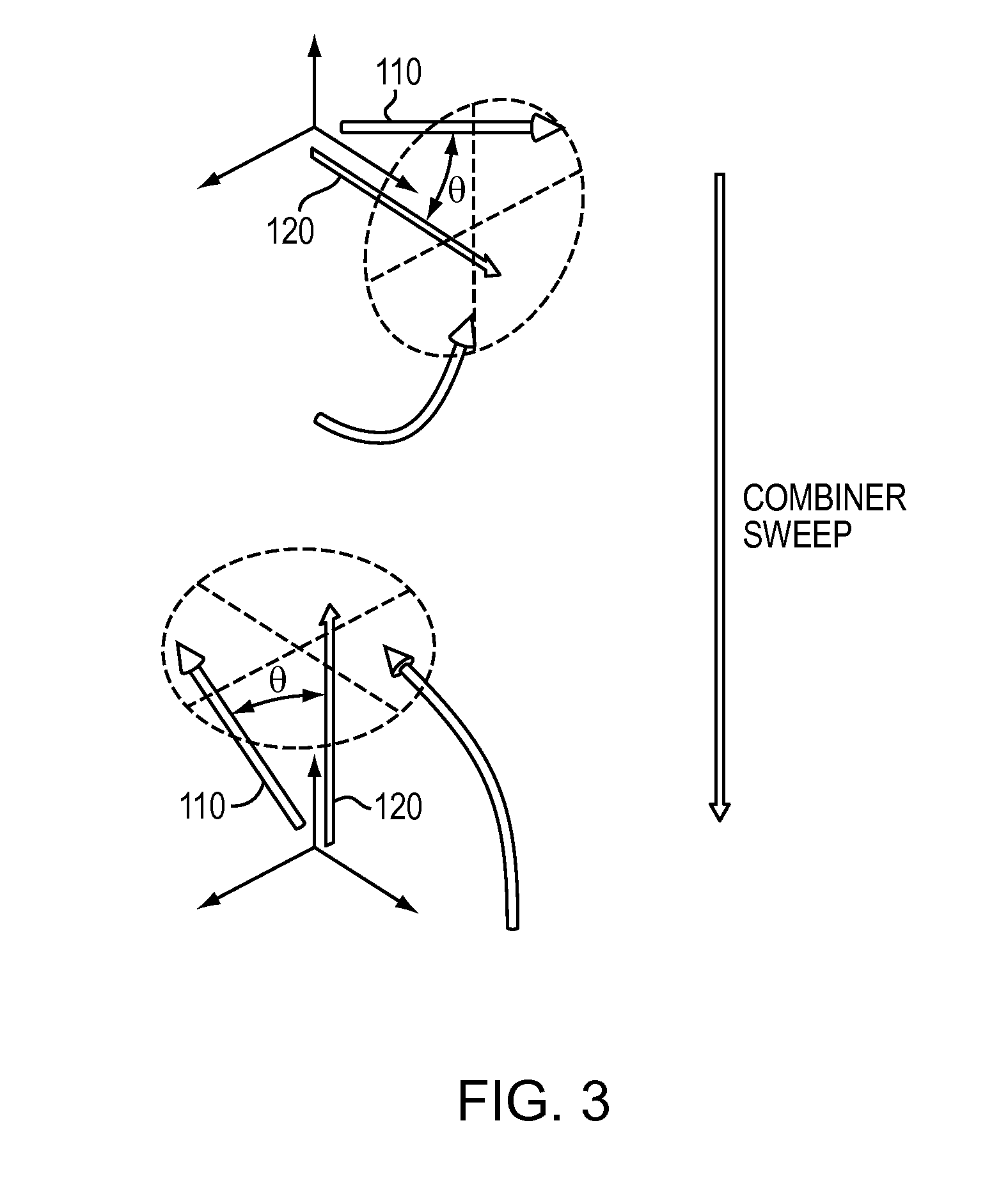
The patent discusses methods and apparatus for transferring coherent atomic populations using laser beam pairs. One technique involves a process called "Raman adiabatic rapid passage" (ARP) which uses characteristic detunings and laser powers in standard Raman pulse beamsplitters. This process results in a sequential transfer of atomic populations and can be combined with standard Raman pulses to create an interferometer. Using ARP sweeps can greatly reduce sensitivity to detuning and AC Stark shifts compared to standard Raman interferometers. The patent also describes inducing transitions between two distinct internal levels of the quantum object by applying and directing coherent electromagnetic energy in pulse form of preselected area, duration, polarization, and time-dependent frequency profile to change the quantum object's momentum.

Problems solved by technology

These variations can be minimized in a laboratory setting, but will be unavoidably larger in dynamic environments, degrading the performance of practical sensors.
In addition, Raman pulses are limited in the thermal velocity range of atoms that can be effectively addressed.

Method used


Image

  • Adiabatic rapid passage atomic beamsplitter using frequency-swept coherent laser beam pairs
  • Adiabatic rapid passage atomic beamsplitter using frequency-swept coherent laser beam pairs
  • Adiabatic rapid passage atomic beamsplitter using frequency-swept coherent laser beam pairs

Examples


example 1

Two Sweep Interferometer Sequences

[0049]This example includes laboratory demonstration of atom interferometry with RCAP sweeps in a two-pulse interferometry sequence using the above-mentioned apparatus. Atom interferometry was done using two-photon transitions between the |F=3; mF=0 and |F=4; mF=0 hyperfine levels. The Raman beam was locked at 2.2 Gigahertz (GHz) above the single-photon resonance, and was passed through an electro-optic modulator (EOM) to create sidebands. Phase modulating the EOM at the hyperfine splitting frequency produced two carrier-sideband pairs, one of which drove the dominant Raman transition in our experiments. The modulated beam carried both Raman frequency components and was circularly polarized to ensure velocity insensitive (co-propagating) transitions. Finally, an arbitrary waveform generator controlled the pulse timing and frequency sweeps for the RCAP process.

[0050]FIG. 5A presents population transfer as a function of the deviation of the center fre...

example 2

Three Sweep Interferometer Sequence

[0053]This example demonstrates atom interferometry with RCAP sweeps in a three-event interferometry sequence with a velocity-sensitive (counter-propagating) Raman beam configuration. As discussed above, the apparatus described in Light pulse atom interferometry at short interrogation times, Butts et al., JOSA B 28, pp 416-421 (2011) was used. As was the case in Example 1, in this example, a Raman master laser was locked at 2.2 GHz above the single-photon resonance, and was passed through an electro-optic modulator (EOM) to create sidebands. Phase modulating the EOM at the hyperfine splitting frequency produced multiple sidebands in addition to the input laser frequency. The modulated beam was applied to two slave lasers, each tuned to principally amplify one of the frequencies required to form a Raman beam pair. The outputs of the slave lasers were applied to oppositely directed optical collimators, which produced counter-propagating Raman laser b...


PUM


Abstract

Methods and apparatus for providing coherent atom population transfer using coherent laser beam pairs in which the frequency difference between the beams of a pair is swept over time. Certain examples include a Raman pulse adiabatic rapid passage sweep regimen configured to be used as a beamsplitter and combiner in conjunction with an adiabatic rapid passage mirror sweep or a standard Raman mirror pulse in a 3-pulse interferometer sequence.

Description

CROSS REFERENCE TO RELATED APPLICATIONS[0001]This application claims the benefit under 35 U.S.C. §119(e) of U.S. Provisional Application No. 61 / 566,209 filed Dec. 2, 2012 and titled “FREQUENCY-SWEPT COHERENT LASER BEAM PAIRS AS ADIABATIC RAPID PASSAGE ATOMIC BEAMSPLITTERS,” which is incorporated herein by reference in its entirety.BACKGROUND[0002]Atom interferometry provides a useful tool for precision measurements in geodesy, inertial navigation, and fundamental physics. In light-pulse atom interferometers, stimulated Raman transitions commonly provide the atom optics that coherently split, reflect, and recombine atom wavepackets. U.S. Pat. No. 5,274,231 and U.S. Pat. No. 5,274,232, each of which is herein incorporated by reference in its entirety, disclose examples of methods and apparatus for manipulating quantum objects, such as atoms, using stimulated Raman transitions. The conventional Raman beamsplitter implementation, which uses resonant pulses to drive atomic transitions, i...

Claims


Application Information

Patent Timeline
IPC IPC(8): H05H3/02G01V7/00
CPCG21K1/003H05H3/02G01V7/00G21K1/006
Inventor STONER, RICHARD E.KINAST, JOSEPH M.TIMMONS, BRIAN P.
Owner CHARLES STARK DRAPER LABORATORY
Learn More