Electric wire, coil, apparatus for designing electric wire, and electric motor
a technology for electric wires and coils, applied in the direction of insulated conductors, cables, instruments, etc., can solve the problems of increasing power consumption, difficult to make the ac resistance of high-frequency wires definitely lower than, and heat generation
- Summary
- Abstract
- Description
- Claims
- Application Information
AI Technical Summary
Benefits of technology
Problems solved by technology
Method used
Image
Examples
first embodiment
Electric Wire Structure
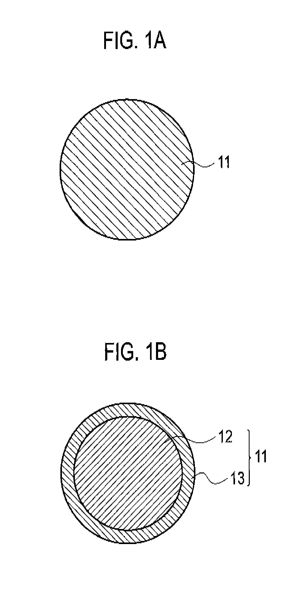
[0101]As shown in FIG. 1A, an electric wire according to a first embodiment of the present invention is an electric wire used in a particular frequency range and includes a conductive portion 11 made of a material having a higher volume resistivity than that of copper. In the electric wire according to the first embodiment of the present invention, the volume resistivity of the conductive portion 11 is specified so that the ratio of the AC resistance due to the proximity effect of the conductive portion 11 to that of a reference Cu wire is less than 1 in the particular frequency range.
[0102]Herein, the particular frequency range refers to a frequency range specified (set) as a frequency range in which the electric wire (product) of interest is used. The upper and lower limits and range of the particular frequency range are properly set according to the specifications of each product and are not particularly limited. The particular frequency range may be about ...
second embodiment
Electric Wire Structure
[0166]An electric wire according to a second embodiment of the present invention is an electric wire used in a particular frequency range. As shown in FIG. 18, the electric wire is a CCA wire including a central conductor 21 made of aluminum (Al) or aluminum alloy and a cover layer 22 made of copper (Cu) covering the central conductor 21. As for the electric wire according to the second embodiment of the present invention, the particular frequency range falls within a frequency range which is specified between the first and second frequencies at which the AC resistance of the electric wire is equal to that of a Cu wire having the same diameter as that of the electric wire and in which the AC resistance of the electric wire is smaller than that of the Cu wire.
[0167]The diameter of the entire electric wire is desirably about 0.05 mm to 0.6 mm. The cross-sectional area of the cover layer 22 is not more than 15% of that of the whole electric wire including the cen...
third embodiment
Electric Wire Structure
[0243]As shown in FIG. 58A, an electric wire according to a third embodiment of the present invention includes a conductive portion 31 made of a material having a volume resistivity higher than that of copper. In the electric wire according to the third embodiment of the present invention, direct current resistance value per unit length, which is obtained by dividing the volume resistivity of the conductive portion 31 by the cross-sectional area thereof, is specified so that, among first and second frequencies at which the AC resistance of the electric wire is equal to that of Cu wire and between which the AC resistance of the electric wire is lower than that of Cu wire, the second frequency is not lower than the upper limit of the particular frequency range.
[0244]The diameter of the conductive portion 31 is desirably about 0.05 mm to 0.6 mm but is not particularly limited. The material of the conductive portion 31 can be copper alloy such as brass, phosphor b...
PUM
| Property | Measurement | Unit |
|---|---|---|
| frequency | aaaaa | aaaaa |
| electric | aaaaa | aaaaa |
| volume resistivity | aaaaa | aaaaa |
Abstract
Description
Claims
Application Information
 - R&D
- Intellectual Property
- Life Sciences
- Materials
- Tech Scout
- Unparalleled Data Quality
- Higher Quality Content
- 60% Fewer Hallucinations
Browse by: Latest US Patents, China's latest patents, Technical Efficacy Thesaurus, Application Domain, Technology Topic, Popular Technical Reports.
© 2025 PatSnap. All rights reserved.Legal|Privacy policy|Modern Slavery Act Transparency Statement|Sitemap|About US| Contact US: help@patsnap.com


