Open-circuit protection circuit of constant current driving circuit for light emitting diodes
a technology of open-circuit protection and driving circuit, which is applied in the direction of electroluminescent light sources, semiconductor lamp usage, electrical lighting sources, etc., can solve the problems of short circuit, increased cost, and short circuit of output capacitors cob>10/b> or cob>20/b>, so as to reduce the cost of open-circuit protection, the effect of reducing the bulk of the current sharing transformer and reducing the stress on the related components of the processing uni
- Summary
- Abstract
- Description
- Claims
- Application Information
AI Technical Summary
Benefits of technology
Problems solved by technology
Method used
Image

Examples
first embodiment
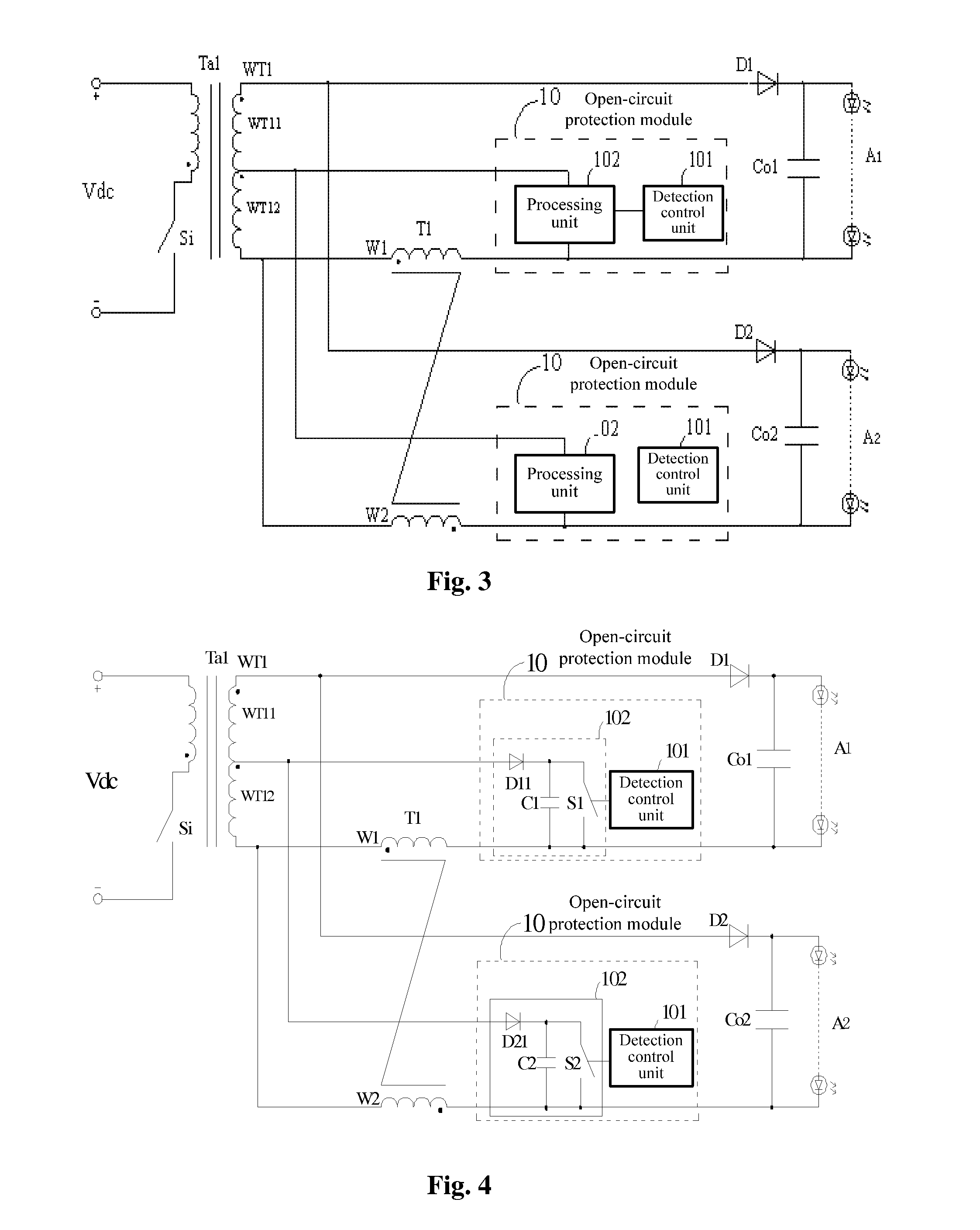
[0085]Reference is made to FIG. 3 which is a circuit diagram of an open-circuit protection circuit of a constant current driving circuit for light emitting diodes according to the invention.
[0086]As shown in FIG. 3, the circuit includes a transformer Ta1.
[0087]A primary side of the transformer Ta1 includes a primary winding and a switch Si. The transformer and the switch Si form a flyback topology circuit. A dotted end of the primary winding of the transformer Ta1 is connected to one terminal of the switch Si, the other terminal of the switch Si is connected to a negative terminal of a power supply Vdc, and an non-dotted end of the primary winding of the transformer Ta1 is connected to a positive terminal of the power supply Vdc.
[0088]A secondary side of the transformer Ta1 includes a first secondary winding WT1 which has two load branches connected with a load A1 and a load A2 respectively. Each of the load branches has a same structure.
[0089]Each of the load branches and the first...
second embodiment
[0107]Reference is made to FIG. 4 which is a circuit diagram of an open-circuit protection circuit of a constant current driving circuit for light emitting diodes according to the invention. FIG. 4 shows an implementation of the processing unit in the circuit shown in FIG. 3. Of course, in other embodiments of the invention, the processing unit can also be implemented in other ways.
[0108]The illustration is made by taking the first load branch as an example. As shown in FIG. 4, the processing unit 102 may include a second diode D11, a first capacitor C1 and a switching device S1. An anode of the second diode D11 is connected to the tap end of the first secondary winding WT1, and a cathode of the second diode D11 is connected to a first terminal of the switching device S1; a second terminal of the switching device S1 is connected to the negative output terminal of the first load branch, and a control terminal of the switching device S1 is connected to a control signal output terminal...
third embodiment
[0111]Reference is made to FIG. 5 which is a circuit diagram of an open-circuit protection circuit of a constant current driving circuit for light emitting diodes according to the invention. FIG. 5 shows an implement of the detection control unit of the open-circuit protection circuit shown in FIG. 4. In FIG. 5, the detection control unit 101 detects the output voltage of each of the load branches. Of course, in other embodiments of the invention, the detection control unit can also be implemented in other ways.
[0112]In the open-circuit protection circuit shown in FIG. 5, the illustration is made also by taking the first load branch as an example. For the open-circuit protection module 10, the detection control unit 101 includes: a zener diode ZD1, a first resistor R11, a second resistor R12, a first filter capacitor Cp1; and the difference of the processing unit 102 from that shown in FIG. 3 is that the switching device S1 is a thyristor S11.
[0113]It should be noted that in the thi...
PUM
 Abstract
Description
Claims
Application Information
 - R&D Engineer
- R&D Manager
- IP Professional
- Industry Leading Data Capabilities
- Powerful AI technology
- Patent DNA Extraction
Browse by: Latest US Patents, China's latest patents, Technical Efficacy Thesaurus, Application Domain, Technology Topic.
© 2024 PatSnap. All rights reserved.Legal|Privacy policy|Modern Slavery Act Transparency Statement|Sitemap