Eureka AIR delivers breakthrough ideas for toughest innovation challenges, trusted by R&D personnel around the world.

High density shielded electrical cable and other shielded cables, systems, and methods

a shielded, high-density technology, applied in the direction of cables, power cables, insulation conductors/cables, etc., can solve the problems of cable flexibility, cable limitations in mass production, and inability to use mass-termination techniques, etc., to increase fabrication speed, reduce complexity, and increase flexibility

Active Publication Date: 2013-06-13
3M INNOVATIVE PROPERTIES CO
View PDF3 Cites 61 Cited by
  • Summary
  • Abstract
  • Description
  • Claims
  • Application Information

AI Technical Summary

Benefits of technology

The patent text describes a cable design that includes multiple conductor sets with only one pair of insulated conductors, which helps to achieve a compact width dimension. The cable can connect to a mini-SAS paddle card, allowing for the accommodation of high-speed shielded transmit and receive pairs using only one ribbon cable. Attaching only one ribbon cable to the paddle card increases fabrication speed, reduces complexity, and allows for increased flexibility and reduced bending radius. The technical effects of this design include improved performance, compact dimensions, and simplified connection methods.

Problems solved by technology

Both these common types of electrical cable normally require the use of specifically designed connectors for termination and are often not suitable for the use of mass-termination techniques, i.e., the simultaneous connection of a plurality of conductors to individual contact elements, such as, e.g., electrical contacts of an electrical connector or contact elements on a printed circuit board.
Although electrical cables have been developed to facilitate these mass-termination techniques, these cables often have limitations in the ability to mass-produce them, in the ability to prepare their termination ends, in their flexibility, and in their electrical performance.

Method used


Image

  • High density shielded electrical cable and other shielded cables, systems, and methods
  • High density shielded electrical cable and other shielded cables, systems, and methods
  • High density shielded electrical cable and other shielded cables, systems, and methods

Examples


example

[0170]A shielded electrical ribbon cable having the general layout of cable 1402 (see FIG. 14) was fabricated. The cable utilized sixteen insulated 32 gauge (AWG) wires arranged into eight twinax pairs for signal wires, and two non-insulated 32 (AWG) wires arranged along the edges of the cable for drain wires. Each of the sixteen signal wires used had a solid copper core with silver plating. The two drain wires each had a stranded construction (7 strands each) and were tin-plated. The insulation of the insulated wires had a nominal outer diameter of 0.025 inches. The sixteen insulated and two non-insulated wires were fed into a device similar to that shown in FIG. 5c, sandwiched between two shielding films. The shielding films were substantially identical, and had the following construction: a base layer of polyester (0.00048 inches thick), on which a continuous layer of aluminum (0.00028 inches thick) was disposed, on which a continuous layer of electrically non-conductive adhesive...

examples

[0184]Two examples are presented in this section. First, two substantially identical untreated shielded electrical ribbon cables were made with the same number and configuration of conductor sets and drain wires as the shielded cable shown in FIG. 21. Each cable was made using two opposed shielding films having the same construction: a base layer of polyester (0.00048 inches thick), on which a continuous layer of aluminum (0.00028 inches thick) was disposed, on which a continuous layer of electrically non-conductive adhesive (0.001 inch thick) was disposed. The eight insulated conductors used in each cable to make the four twinax conductor sets were 30 gauge (AWG), solid core, silver plated copper wire. The eight drain wires used for each cable were 32 gauge (AWG), tin-plated, 7-stranded wires. The settings used for the manufacturing process were adjusted so that a thin layer (less than 10 micrometers) of the adhesive material (a polyolefin) remained between each drain wire and each...


PUM

PropertyMeasurementUnit
frequencyaaaaaaaaaa
widthaaaaaaaaaa
widthaaaaaaaaaa

Abstract

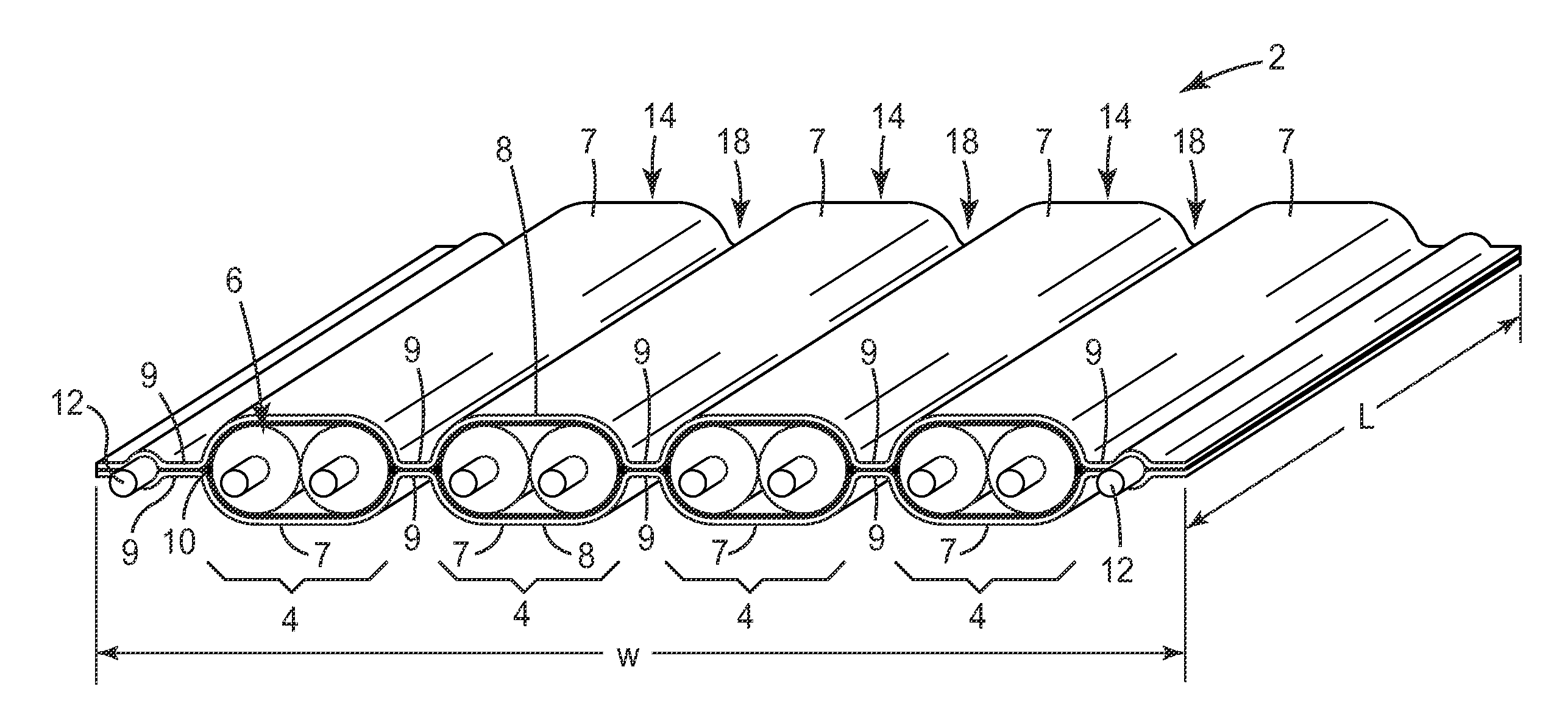
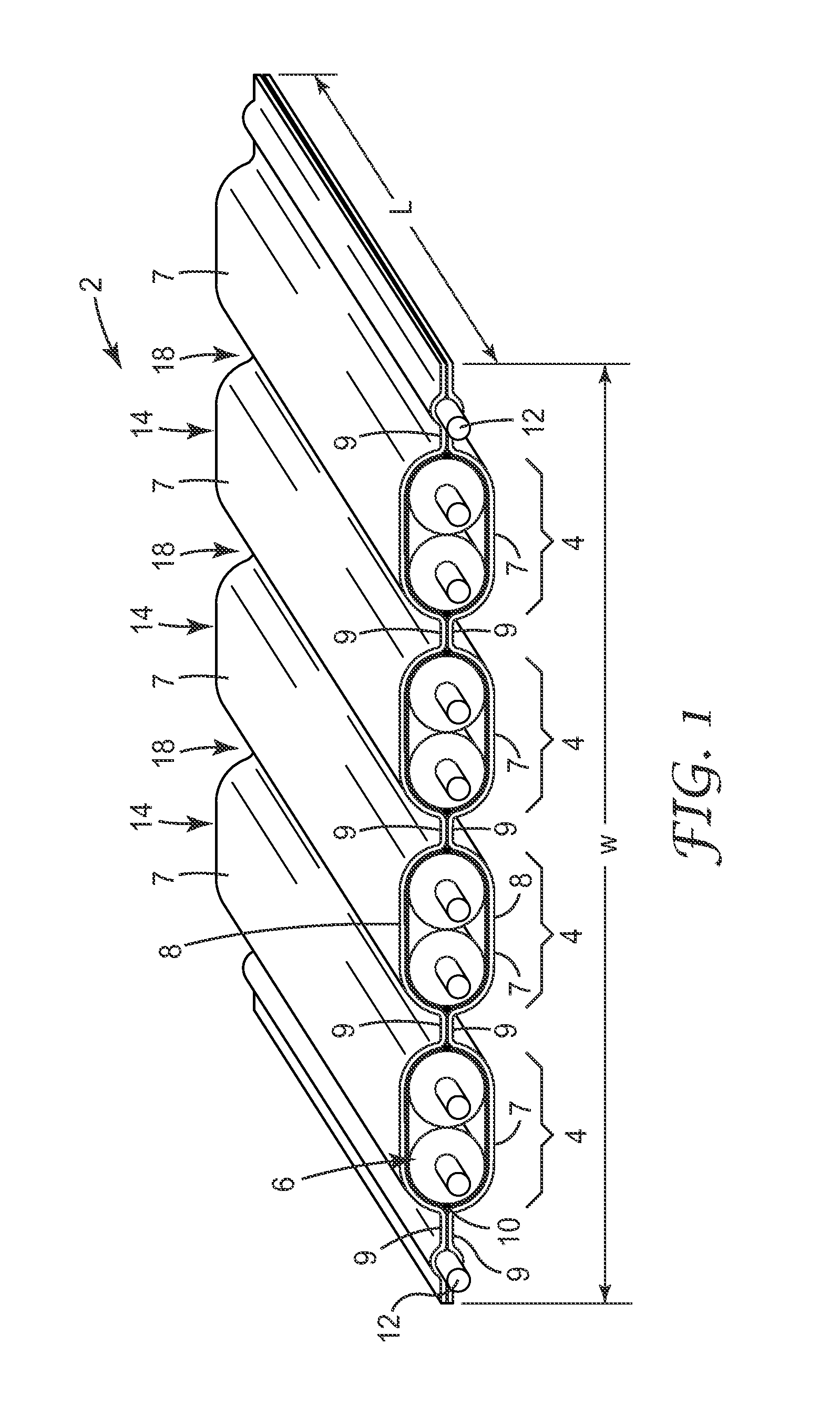
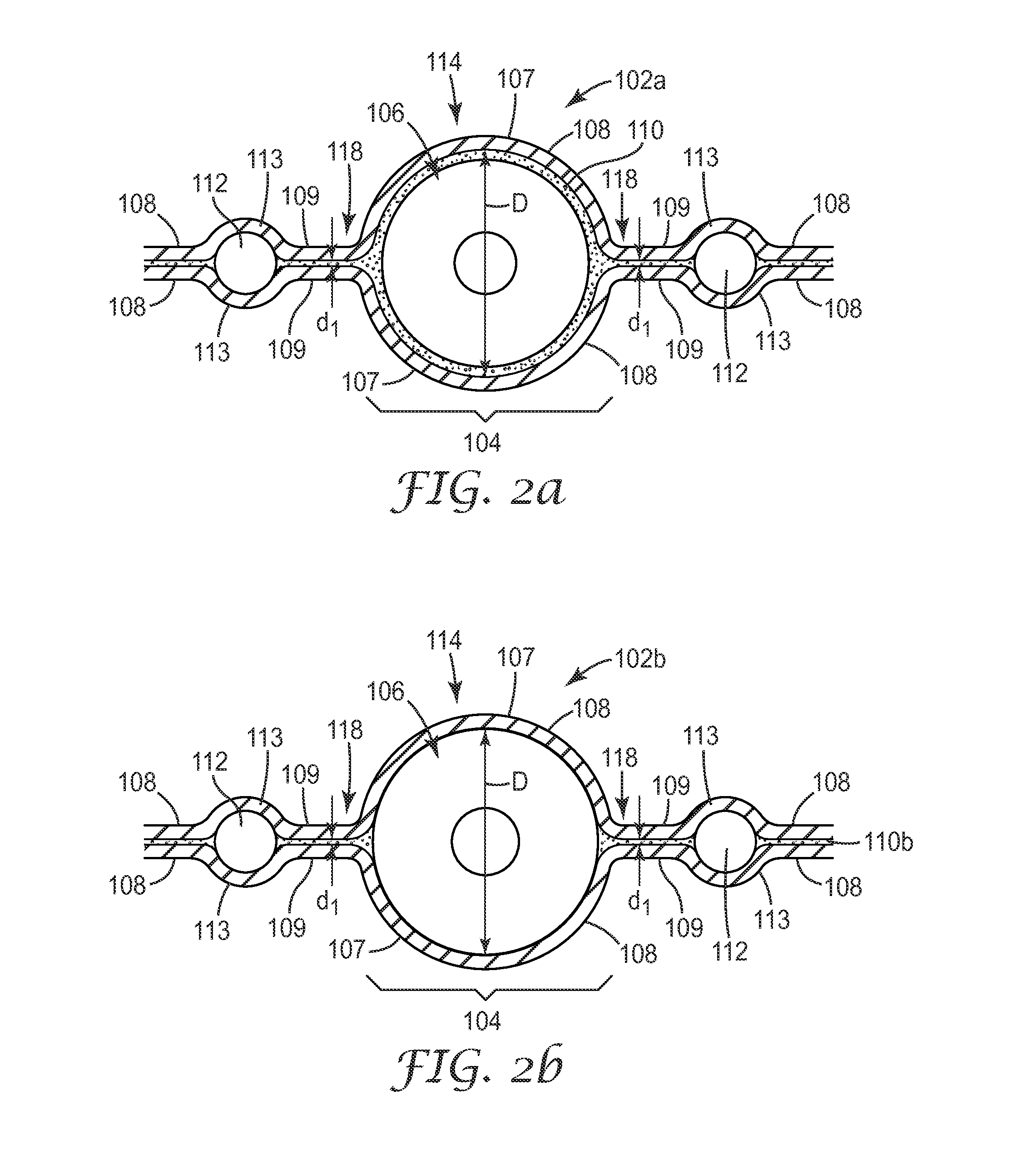
A shielded electrical ribbon cable (2) includes conductor sets (4) each including one or more insulated conductors (6), and a first and second shielding film (8) on opposite sides of the cable. In transverse cross section, cover portions (7) of the shielding films (8) substantially surround each conductor set (4), and pinched portions (9) of the films (8) form pinched portions of the cable on each side of each conductor set (4). Dense packing is achieved while maintaining high frequency electrical isolation between conductor sets (4). When the cable (2) is laid flat, a quantity s / Dmin is in a range from 1.7 to 2, where S is a center-to-center spacing between nearest insulated conductors (6) of two adjacent conductor sets (4), and Dmin is the lesser of the outer dimensions of such nearest insulated conductors (6). Alternatively, a first and second conductor set each having only one pair of insulated conductors can satisfy a condition that Σ / σ1 is in a range from 2.5 to 3. Other shielded cables, systems, and methods, which may or may not utilize the dense packing, are also disclosed.

Description

FIELD OF THE INVENTION[0001]This invention relates generally to shielded electrical ribbon cables suitable for data transmission and associated articles, systems, and methods, with particular application to ribbon cables that can be mass-terminated and provide high speed electrical properties.BACKGROUND[0002]Electrical cables for transmission of electrical signals are known. One common type of electrical cable is a coaxial cable. Coaxial cables generally include an electrically conductive wire surrounded by an insulator. The wire and insulator are surrounded by a shield, and the wire, insulator, and shield are surrounded by a jacket. Another common type of electrical cable is a shielded electrical cable comprising one or more insulated signal conductors surrounded by a shielding layer formed, for example, by a metal foil. To facilitate electrical connection of the shielding layer, a further un-insulated conductor is sometimes provided between the shielding layer and the insulation o...

Claims


Application Information

Patent Timeline
Patent Type & Authority Applications(United States)
IPC IPC(8): H01B7/08
CPCH01B7/0838H01B11/002H01B11/203H01B7/0861H01B7/0823H01B11/1891H01B11/1895H01B11/005H01B11/1066H01B11/1091H01B13/14H01B7/0807
Inventor GUNDEL, DOUGLAS B.EDWARDS, ROCKY D.LETTANG, MARK M.STALEY, CHARLES F.
Owner 3M INNOVATIVE PROPERTIES CO
Why Eureka
Eureka Blog
Learn More