
Method for producing a thin single crystal silicon having large surface area

Inactive Publication Date: 2013-06-06
NAT TAIWAN UNIV
View PDF3 Cites 21 Cited by
  • Summary
  • Abstract
  • Description
  • Claims
  • Application Information

AI Technical Summary

Benefits of technology

The present invention provides a method for producing thin single crystal silicon with large surface area, using a simplified process. This method allows for the formation of microstructures or nanostructures on a substrate, which can be transferred to another substrate or formed as an independent thin film silicon. This recycling of substrates reduces waste and lowers production costs. The patent text also mentions that the patterned mask or metal barrier layer on the substrate can be designed to have different patterns and shapes, allowing for the formation of electronic components and circuits which can be lifted off to form a thin integrated circuit. This material can be utilized in various applications and can be placed on non-planar objects due to its flexibility. Additionally, the invention provides a simplified method to transfer the silicon microstructures, nanostructures, or thin film semiconductor materials from the substrate and recycle the substrate again or repeatedly, reducing production costs and simplifying the process.

Problems solved by technology

The dry etching also needs to be performed in high vacuum and it also needs an expensive device.
However, whether above-mentioned expensive method for producing the silicon micro and nanostructures or the wet etching having an advantage of low cost is applied, most of silicon micro and nanostructures having good quality of crystal lattice need to be formed on a silicon substrate.

Method used


Image

  • Method for producing a thin single crystal silicon having large surface area
  • Method for producing a thin single crystal silicon having large surface area
  • Method for producing a thin single crystal silicon having large surface area

Examples


Embodiment Construction

[0017]The detailed description of the present invention will be discussed in the following embodiments, which are not intended to limit the scope of the present invention, and can be adapted for other applications. While drawings are illustrated in detail, it is appreciated that the quantity of the disclosed components may be greater or less than that disclosed, except where expressly restricting the amount of the components. Although specific embodiments have been illustrated and described, it will be appreciated by those skilled in the art that various modifications may be made without departing from the scope of the present invention, which is intended to be limited solely by the appended claims.

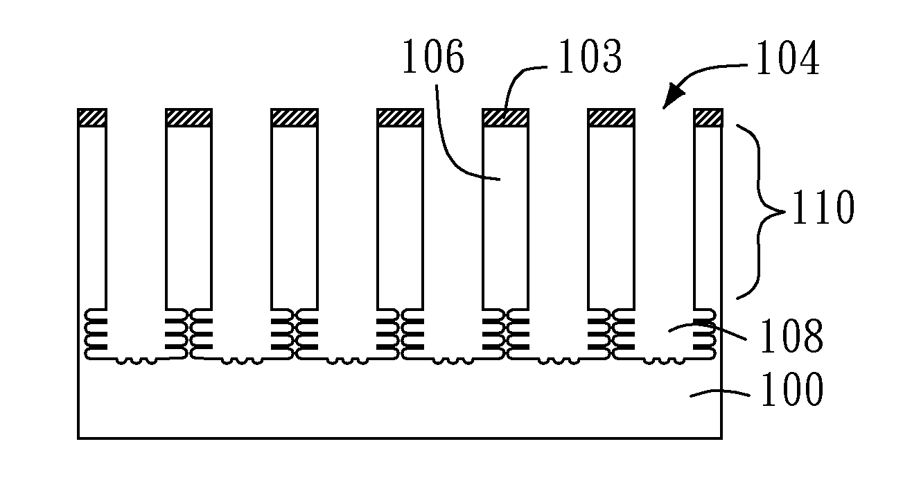
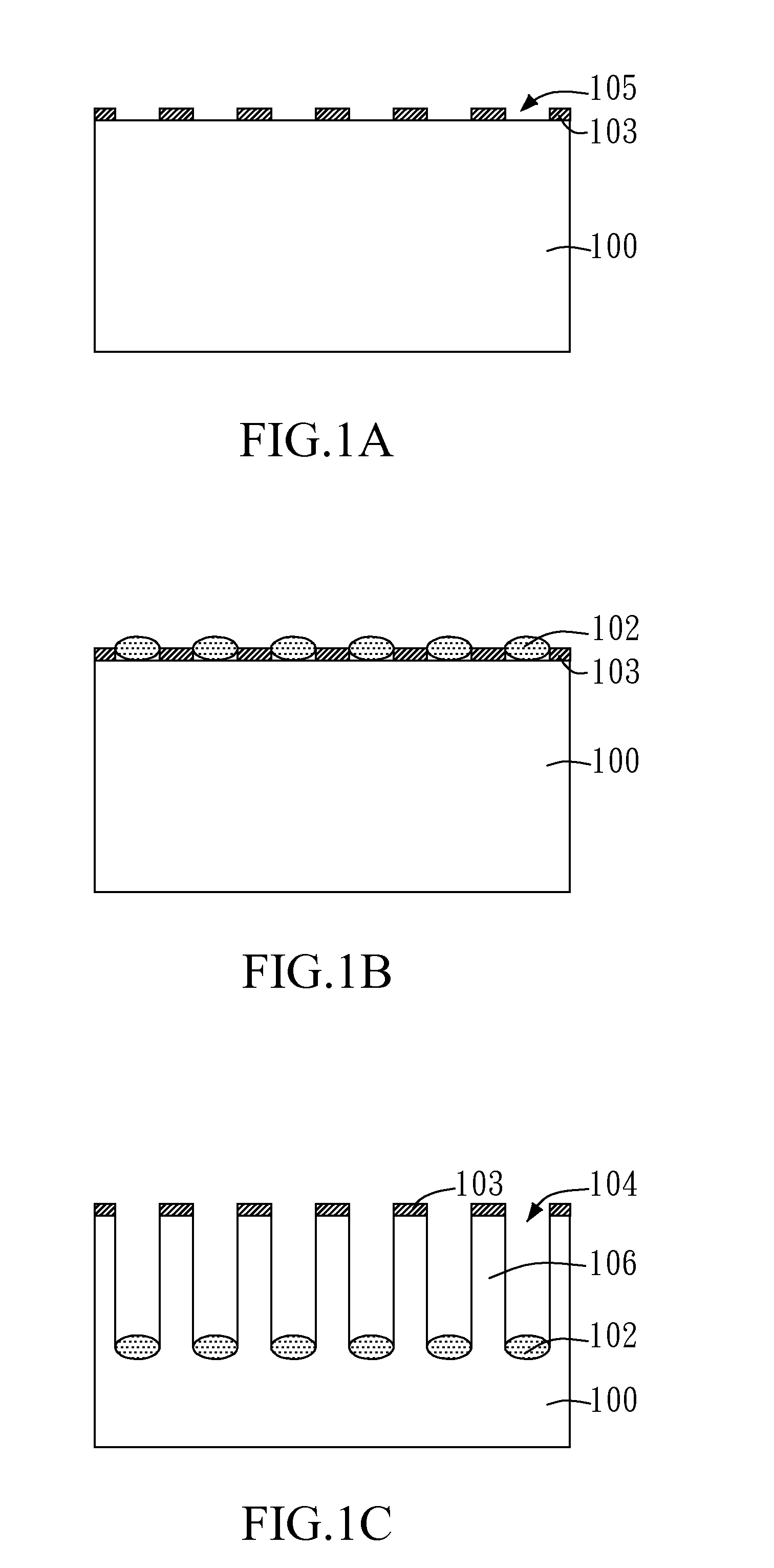
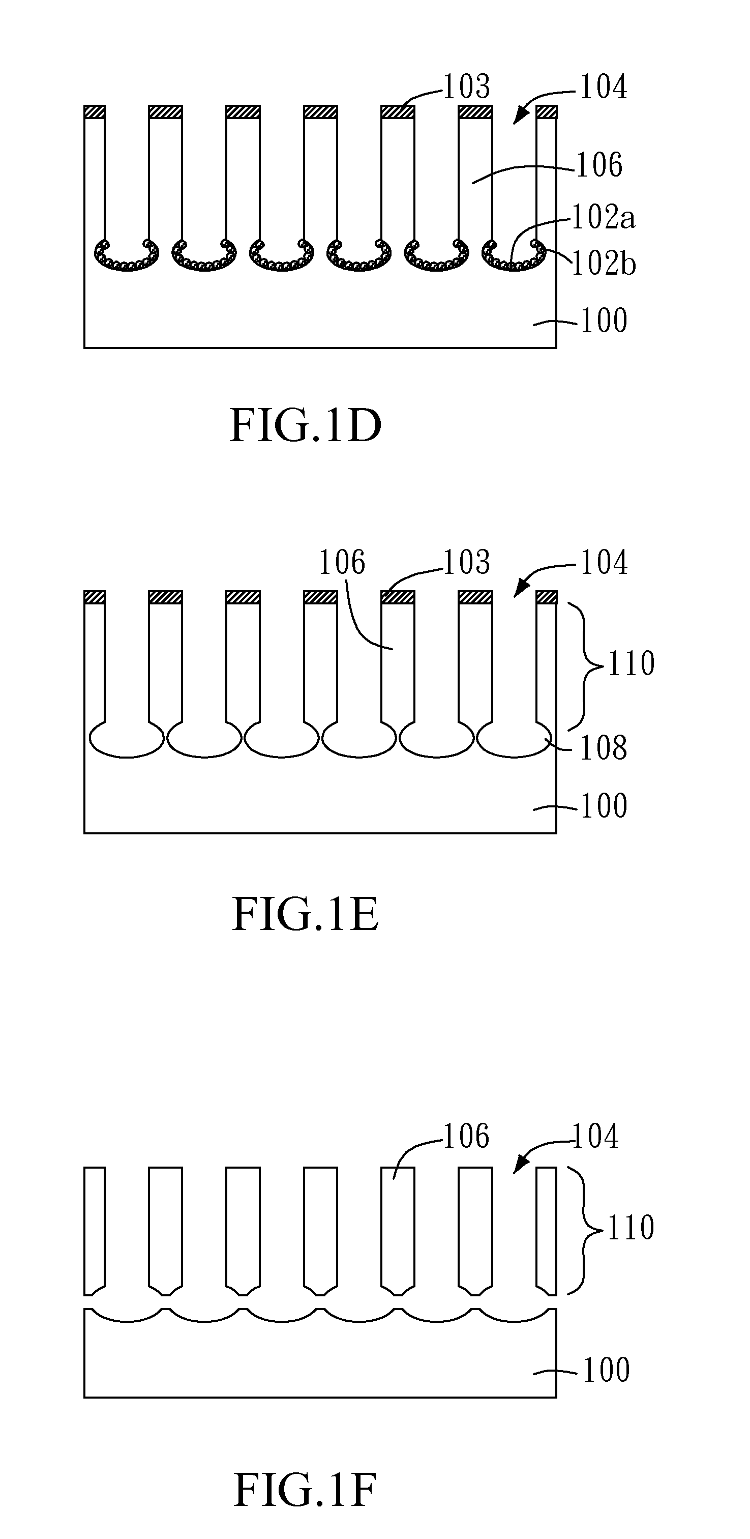
[0018]FIG. 1A to FIG. 1F are a series of cross-section drawings illustrating a method for producing a thin single crystal silicon having large surface area in accordance with an embodiment of the present invention. Referring to FIG. 1A, first, a substrate 100 made of a single material is ...


PUM


Abstract

The present invention relates to a method for producing a thin single crystal silicon having large surface area, and particularly relates to a method for producing a silicon micro and nanostructure on a silicon substrate (or wafer) and lifting off the silicon micro and nanostructure from the silicon substrate (or wafer) by metal-assisted etching. In this method, a thin single crystal silicon is produced in the simple processes of lifting off and transferring the silicon micro and nanostructure from the substrate by steps of depositing metal catalyst on the silicon wafer, vertically etching the substrate, laterally etching the substrate. And then, the surface of the substrate is processed, for example planarizing the surface of the substrate, to recycle the substrate for repeatedly producing thin single crystal silicons. Therefore, the substrate can be fully utilized, the purpose of decreasing the cost can be achieved and the application can be increased.

Description

CROSS-REFERENCE TO RELATED APPLICATIONS[0001]The entire contents of Taiwan Patent Application No. 100144941, filed on Dec. 6, 2011, from which this application claims priority, are incorporated herein by reference.BACKGROUND OF THE INVENTION[0002]1. Field of the Invention[0003]The present invention relates to a method for producing a thin single crystal silicon having large surface area, and particularly relates to a method for producing a silicon micro and nanostructure on a silicon substrate (or wafer) and lifting off the silicon micro and nanostructure from the silicon substrate (or wafer) by metal-assisted etching.[0004]2. Description of Related Art[0005]Currently, thin single crystal silicon, for example silicon microstructure and silicon nanostructure (or called silicon micro and nanostructure for short), is applied in many fields. For example, waveguides or lasers of photoelectric field, antireflection layers or PN junctions of solar cell, and electronic components (such as t...

Claims


Application Information

Patent Timeline
IPC IPC(8): H01L21/311B82Y40/00
CPCB81C1/00B81C1/0038B81C99/008B81B2207/056B81C2201/0194
Inventor LIN, CHING-FUHLIN, TZU-CHINGSYU, SHU-JIA
Owner NAT TAIWAN UNIV
Learn More