
Method for charging a rechargeable energy store, charging device for a rechargeable energy store, and circuit breaker

harging device technology, applied in the direction of electric devices, battery overheat protection, safety/protection circuits, etc., can solve the problem of power supply line overloaded, and achieve the effect of expanding the advantages of a conventional charging device and increasing the reliability of recharging a rechargeable energy stor

Active Publication Date: 2013-06-06
ROBERT BOSCH GMBH
View PDF4 Cites 10 Cited by
  • Summary
  • Abstract
  • Description
  • Claims
  • Application Information

AI Technical Summary

Benefits of technology

The present invention is a battery charger for electric and hybrid vehicles that can adapt to different power needs. It ensures reliable charging even if there are issues with the power supply. This is achieved by adjusting the charging operation based on the current capacity utilization of the power supply and the charging of other energy stores. The charging device can also determine the battery storage capacity during recharging, taking into account the operativeness of the battery. Overall, the invention expands the benefits of conventional charging devices.

Problems solved by technology

Normally, when an energy store is charged by a charging current drawn from a power supply line, a circuit breaker (overload device) of the power supply line is often tripped, or, if it is not equipped with the circuit breaker, the power supply line is often overloaded.

Method used


Image

  • Method for charging a rechargeable energy store, charging device for a rechargeable energy store, and circuit breaker
  • Method for charging a rechargeable energy store, charging device for a rechargeable energy store, and circuit breaker
  • Method for charging a rechargeable energy store, charging device for a rechargeable energy store, and circuit breaker

Examples


Embodiment Construction

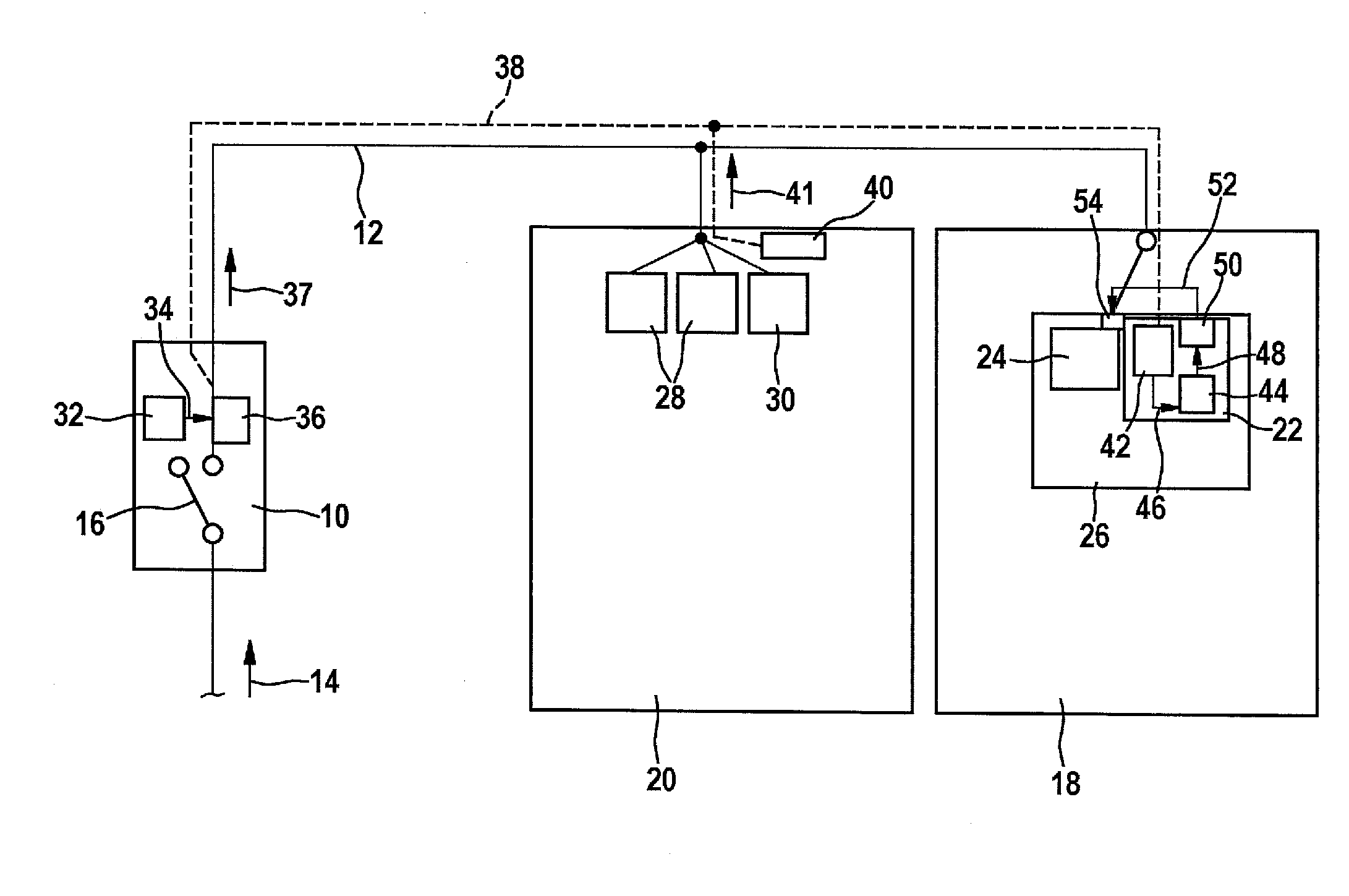
[0012]FIG. 1 shows a flow chart for illustrating a specific embodiment of the method for charging a rechargeable energy store.

[0013]In a preceding method step S0, the rechargeable energy store, for example, a battery, in particular, a vehicle battery, is coupled to a power supply line. As explained below in more detail, the method described here is designed in such a manner, that no particular requirements are to be set for the utilized power supply line for charging the rechargeable energy store. For example, in order to charge the energy store, it is no longer necessary to use a power supply line, in which a comparatively high, minimum current intensity over a certain, minimum time is ensured without an overload of the power supply line. The power supply line may be, in particular, a power supply line, which is installed in a residential building, and to which a plurality of load circuits, such as the usual household devices, are connected. In general, the coupling of the recharge...


PUM


Abstract

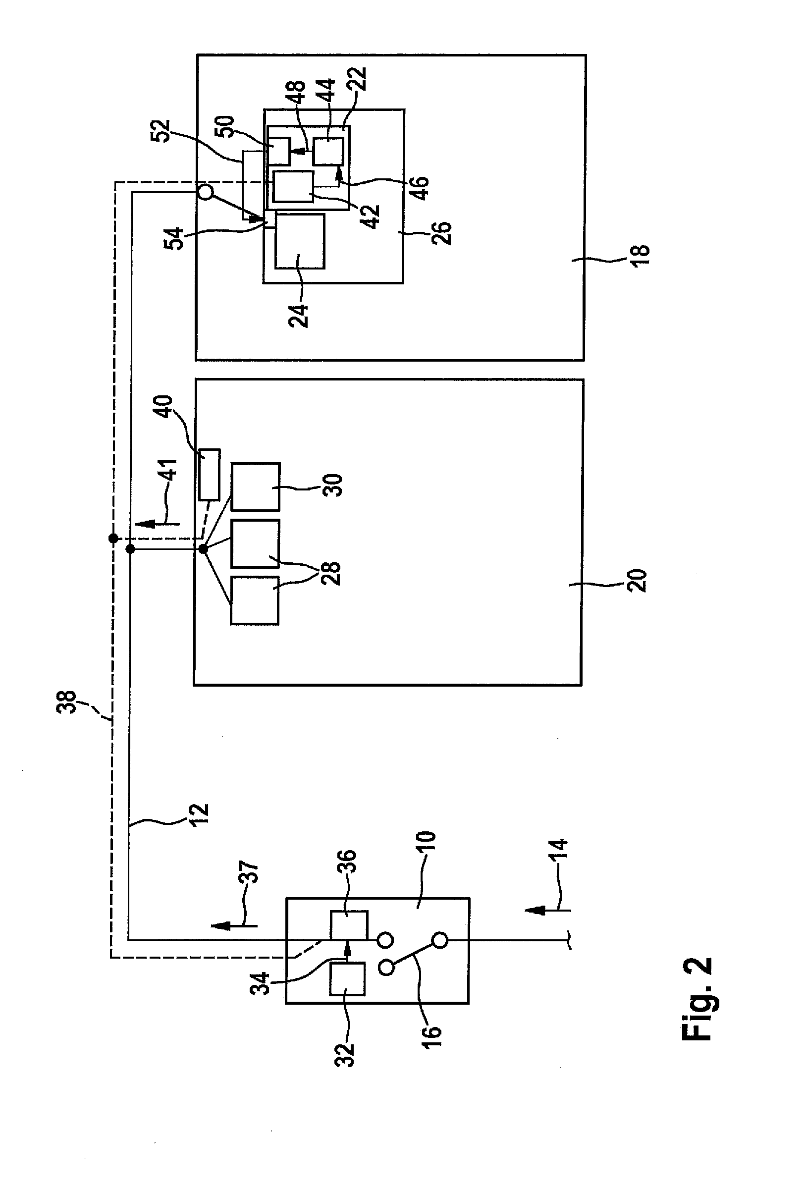
A method for charging a rechargeable energy store (24), having the steps: coupling the rechargeable energy store (24) to a power supply line (10); ascertaining a piece of utilization information (34) regarding a capacity utilization of a tripping load of a circuit breaker (10) coupled to the power supply line (12); and / or ascertaining a separate piece of charging information (41) regarding a power and / or a time remaining of a separate charging current supplied to a further energy store (30) by the power supply line (12); setting at least one selection variable (48) regarding a time characteristic of a setpoint current intensity of a setpoint charging current supplied by the power supply line (12) to the rechargeable energy store (24), in view of the ascertained utilization information (24) and / or the ascertained, separate charging information (41); and applying a charging current from the power supply line (12) to the rechargeable energy store (24) in view of the at least one set selection variable (48). In addition, the invention relates to a charging device (22) for a rechargeable energy store (24). Furthermore, the invention relates to a circuit breaker (10).

Description

[0001]The present invention relates to a method for charging a rechargeable energy store. In addition, the present invention relates to a charging device for a rechargeable energy store. Furthermore, the present invention relates to a circuit breaker.BACKGROUND INFORMATION[0002]DE 10 2007 038 376 A1 describes a charging device for charging a battery. With the aid of the charging device, a charging current may be made available by a power supply line, to which the battery may be coupled. In addition, the described charging device is intended to have the function of determining the battery storage capacity. By determining the battery storage capacity, it should be able to be detected if sufficient operability of the battery is ensured.SUMMARY OF THE INVENTION[0003]The present invention provides a method for charging a rechargeable energy store, having the features of claim 1, a charging device for a rechargeable energy store, having the features of claim 4, and a circuit breaker havin...

Claims


Application Information

Patent Timeline
Patent Type & Authority Applications(United States)
IPC IPC(8): H02J7/00H02H3/08B60L11/18
CPCB60L3/04B60L11/1816B60L2240/36H02J7/0026H02J7/007H02H3/085Y02T10/7055Y02T90/14B60L3/0069B60L11/1809Y02T10/7005Y02T10/7072B60L53/14B60L53/00Y02T10/70H02J7/0029H02J7/00304H02J7/00309
Inventor KILB, JOCHEN
Owner ROBERT BOSCH GMBH
Learn More