
System and method for energy management in an electric vehicle

a technology of energy management and electric vehicles, applied in the direction of battery/fuel cell control arrangement, propulsion by capacitors, instruments, etc., can solve the problems of shortening the life of the battery, affecting the efficiency of the battery, and generally operating with limited or no information about the environment and vehicle usage, etc., to achieve the effect of optimizing the usage of energy storage components

Active Publication Date: 2013-05-30
GENERAL ELECTRIC CO
View PDF27 Cites 59 Cited by
  • Summary
  • Abstract
  • Description
  • Claims
  • Application Information

AI Technical Summary

Benefits of technology

The invention is a system and method for optimizing energy storage in vehicles. It includes an energy management system that determines the net total power of the vehicle, which is a combination of the traction drive load demand, auxiliary device load demand, and regenerative power. The system then provides power to the vehicle's power source and energy source based on the net total power demand. The system can also selectively provide charging power to the high specific-power energy storage device and the high specific-energy energy storage device, based on the vehicle's net power supply or power load. The technical effects of this invention include improved energy storage efficiency and optimization of power usage in vehicles.

Problems solved by technology

However, prior art energy storage device arrangements generally operate with limited or no information about the environment and vehicle usage and lack a sophisticated control scheme.
This often results in sub-optimal usage of the energy storage devices that can shorten life because of unnecessary applied stresses, with efficiencies of the energy storage devices not being optimized during charging and discharging events.
Additionally, energy storage devices are over-sized for the application to ensure that stress limits are not exceeded, which adds cost to the system.

Method used


Image

  • System and method for energy management in an electric vehicle
  • System and method for energy management in an electric vehicle
  • System and method for energy management in an electric vehicle

Examples


Embodiment Construction

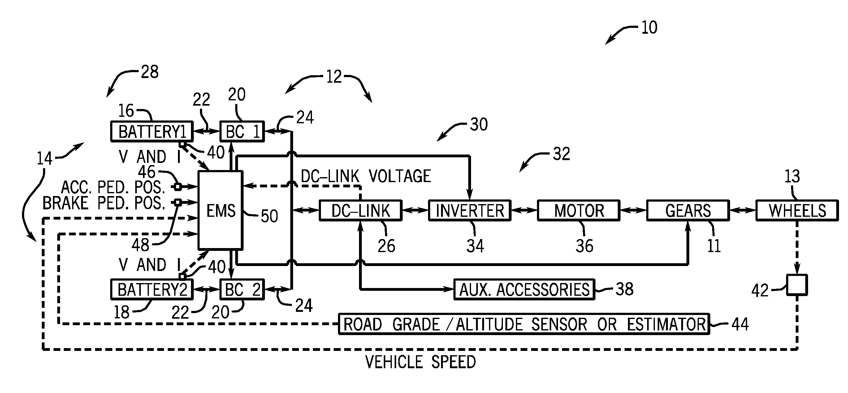
[0017]The invention includes embodiments that relate to optimization of energy storage component usage. The invention includes embodiments that relate to systems and methods of energy management and optimization of energy storage component usage for a vehicle. The invention is described with respect to a multi-energy storage electric vehicle. The embodiments and methods illustrated herein may also be applied to hybrid vehicles, range extended electric vehicles, plug-in hybrid electric vehicles (PHEV), and the like. The embodiments and methods illustrated herein may be broadly applied to passenger and commercial vehicles as well as to locomotives, off-highway vehicles, roller coaster systems, ships and planes. It should also be understood that a vehicular implementation is only one of many uses for this technology. Any system containing power generation, consumption, and energy storage components is a candidate for incorporating embodiments of the invention.

[0018]FIG. 1 illustrates a...


PUM


Abstract

A vehicular energy management system (EMS) determines a net total power from a traction drive load, an auxiliary device load, and a regenerative power. If the net total power is a net supply power, the EMS causes regenerative power to be provided to a power source and energy source in a controlled manner to initially charge the power source to a desired state-of-charge (SOC) and then subsequently charge the energy source. If the net total power comprises a net power load, the EMS causes power to be drawn from the power source and the energy source, with a split of the power being drawn from the power source and the energy source being based on a magnitude of the net power load. The EMS adjusts / maintains the SOC set-point of the power source and the DC link voltage based on vehicle speed and relative altitude of travel of the vehicle.

Description

BACKGROUND OF THE INVENTION[0001]The invention relates generally to hybrid and electric vehicles, and more specifically to a system and method of energy management and optimization of energy storage component usage aboard hybrid and electric vehicles.[0002]Electric vehicles and hybrid electric vehicles are typically powered by one or more energy storage devices, either alone or in combination with an internal combustion engine. In pure electric vehicles, the one or more energy storage devices power the entire drive system, thereby eliminating the need for an internal combustion engine. Hybrid electric vehicles, on the other hand, include energy storage device power to supplement power supplied by an internal combustion engine, which greatly increases the fuel efficiency of the internal combustion engine and of the vehicle. Traditionally, the energy storage devices in electric or hybrid electric propulsion systems include batteries, ultracapacitors, flywheels, superconducting magneti...

Claims


Application Information

Patent Timeline
Patent Type & Authority Applications(United States)
IPC IPC(8): G06F7/00
CPCG06F7/00B60L2200/26B60L11/18B60L1/00B60L7/14B60L2210/30B60L2210/40B60L2240/12B60L2240/421B60L2240/423B60L2240/547B60L2240/549B60L2240/642B60L2250/26Y02T90/16B60L50/40B60L58/13B60L58/20Y02T10/64Y02T10/70Y02T10/72
Inventor SHI, RUIJIEKING, ROBERT DEANGEMIN, PAUL ROBERTBERRY, IRENE MICHELLEESPINEL PORRAS, AUGUSTO
Owner GENERAL ELECTRIC CO
Learn More