Method of manufacturing semiconductor device having plural semiconductor chips stacked one another
a semiconductor chip and stacked technology, applied in semiconductor devices, semiconductor/solid-state device details, electrical devices, etc., can solve the problems of chip cracks, inability to manage external dimensions, and concern that stress may be applied to thin semiconductor chips, so as to reduce the stress of the underfill material, prevent the variation of the outer shape and improve the resistance of the second chip laminated body
- Summary
- Abstract
- Description
- Claims
- Application Information
AI Technical Summary
Benefits of technology
Problems solved by technology
Method used
Image
Examples
first embodiment
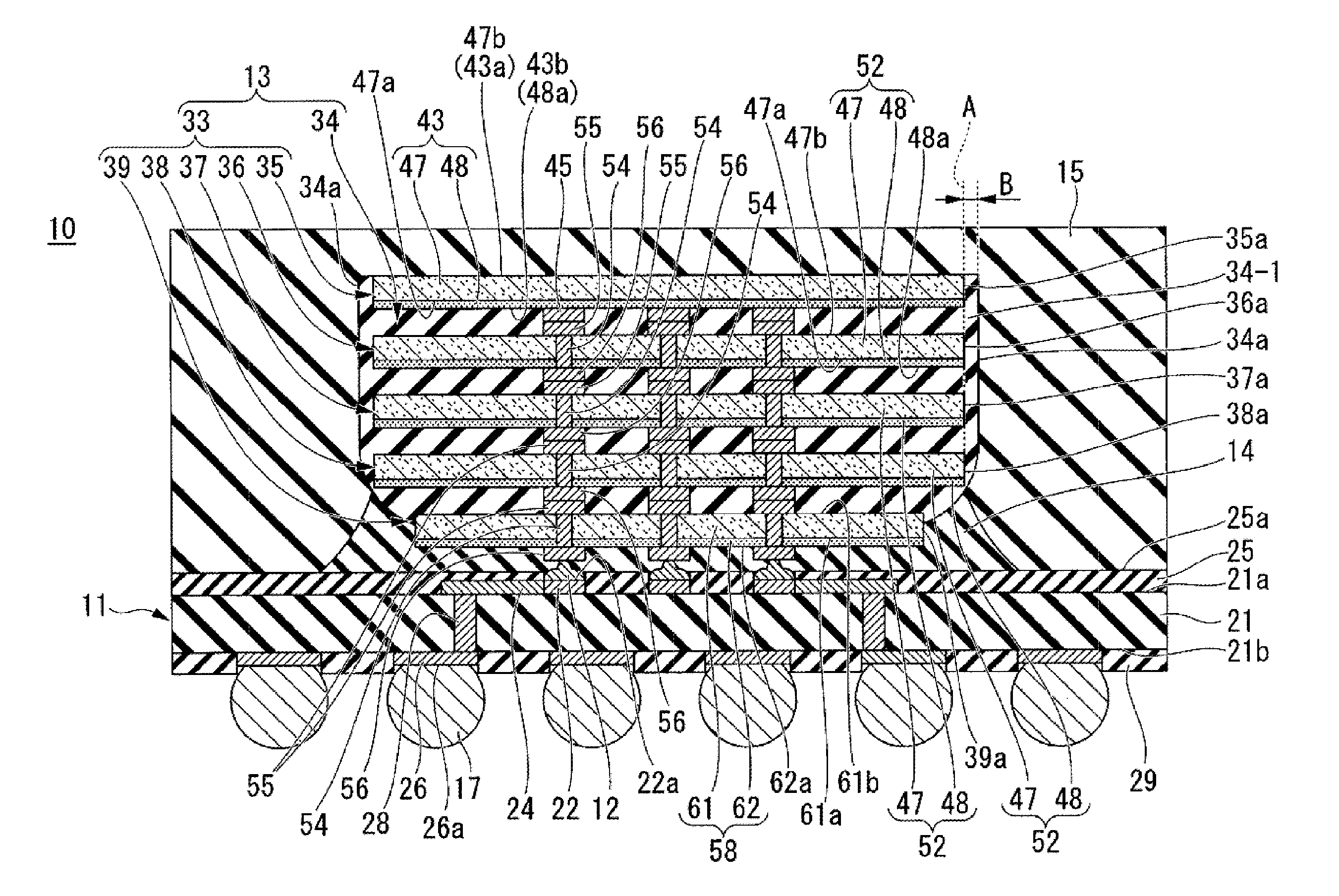
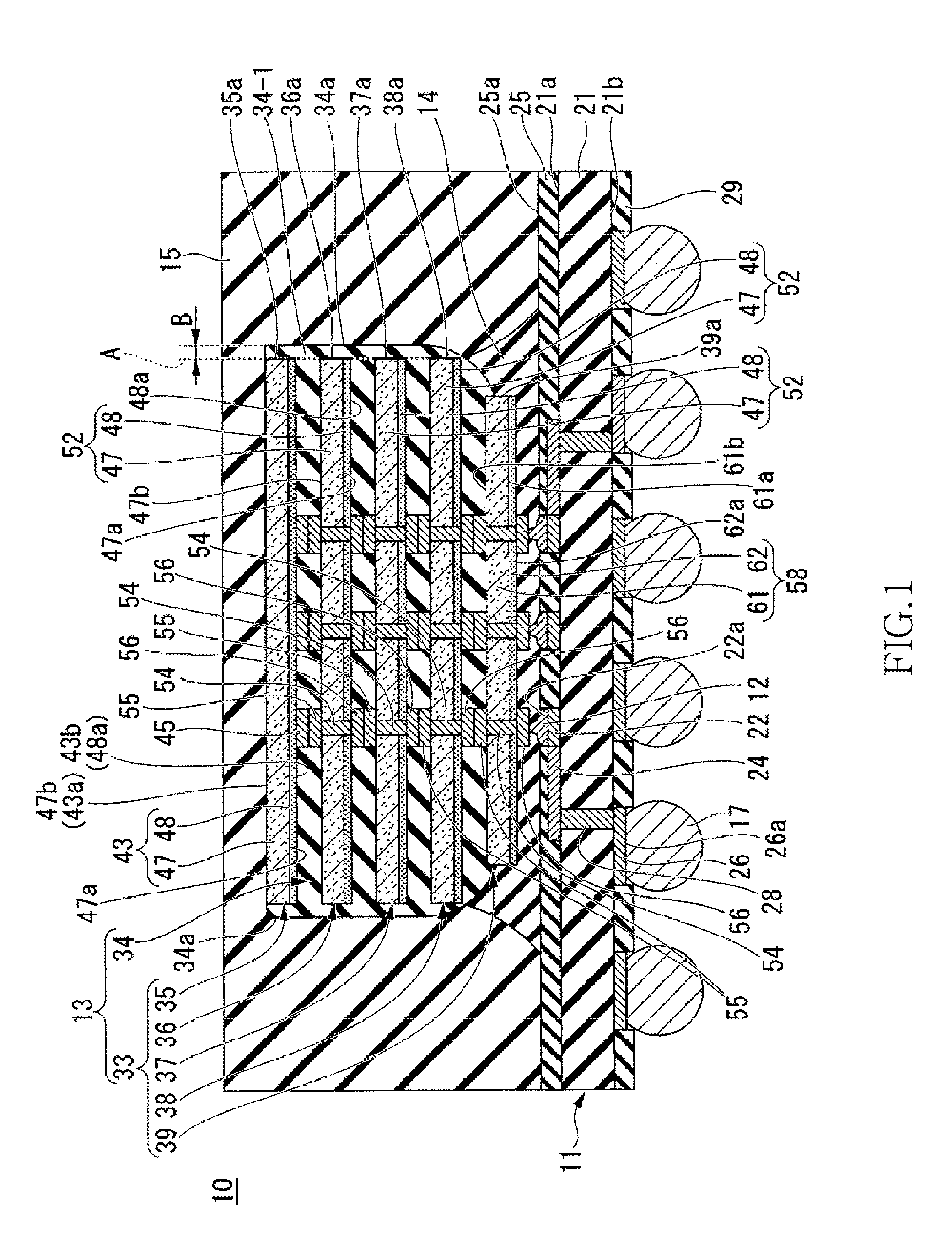
[0025]Referring now to FIG. 1, a semiconductor device 10 of the first embodiment is a semiconductor device of a CoC (Chip on Chip) type. The semiconductor device 10 includes a wiring substrate 11, wire bumps 12, a chip laminated body 13 with an underfill material, a first sealing resin 14, a second sealing resin 15, and external connection terminals 17.
[0026]The wiring substrate 11 includes a wiring substrate body 21, connection pads 22, wirings 24, a first solder resist 25, external connection pads 26, penetration electrodes 28, and a second solder resist 29.
[0027]The wiring substrate body 21 is an insulating substrate that is in the shape of a rectangle, and has a flat surface 21a (principal surface of the wiring substrate 11), and a back surface 21b. For the wiring substrate body 21, for example, a glass epoxy board may be used.
[0028]The connection pads 22 are provided in a central portion of the surface 21a of the wiring substrate body 21. The connection pads 22 are so disposed ...
second embodiment
[0195]A semiconductor device according to a second embodiment of the present invention will be explained with reference to FIG. 17. In FIG. 17, the same components as those of the semiconductor device 10 of the first embodiment are represented by the same reference symbols.
[0196]As shown in FIG. 17, the semiconductor device 110 of the second embodiment has the same configuration as the semiconductor device 10 except that: instead of the wiring substrate 11 that is provided in the semiconductor device 10 of the first embodiment, a wiring substrate 111 is provided; and that a logic semiconductor chip 113, a plurality of metal wires 114, and an adhesive 115 are provided.
[0197]The wiring substrate 111 has the same configuration as the wiring substrate 11 described in the first embodiment except that: the connection pads 22 are disposed at the outer periphery of the surface 21a of the wiring substrate body 21; the wirings 24 are disposed on the back surface 21b of the wiring substrate bo...
third embodiment
[0221]A semiconductor device according to a third embodiment of the present invention will be explained with reference to FIG. 18. In FIG. 18, the same components as those of the semiconductor device 10 of the first embodiment are represented by the same reference symbols.
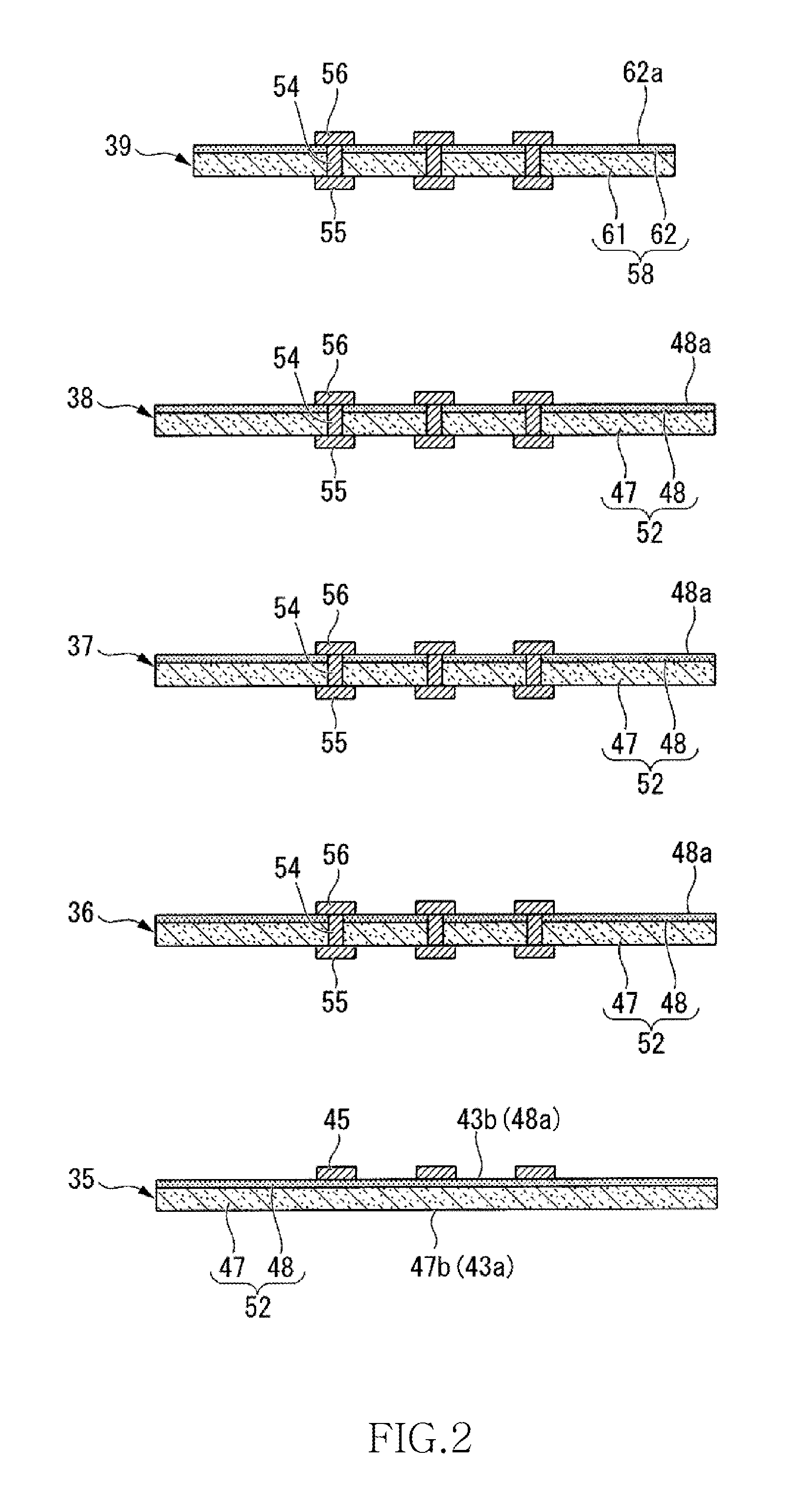
[0222]As shown in FIG. 18, the semiconductor device 200 of the present embodiment is different from the semiconductor device 100 of the first embodiment shown in FIG. 1 mainly in that: the chip laminated body 13 with the underfill material shown in FIG. 1 is replaced with a chip laminated body 220 with an underfill material; and the second semiconductor chip 39 is replaced with a third semiconductor chip 230.
[0223]The chip laminated body 220 with the underfill material includes a chip laminated body 210 and an underfill material 34.
[0224]The chip laminated body 210 is made up of the first semiconductor chip 35 and a plurality of second semiconductor chips 36 to 38. Similarly to the first embodiment, for the semicon...
PUM
 Abstract
Description
Claims
Application Information
 - R&D
- Intellectual Property
- Life Sciences
- Materials
- Tech Scout
- Unparalleled Data Quality
- Higher Quality Content
- 60% Fewer Hallucinations
Browse by: Latest US Patents, China's latest patents, Technical Efficacy Thesaurus, Application Domain, Technology Topic, Popular Technical Reports.
© 2025 PatSnap. All rights reserved.Legal|Privacy policy|Modern Slavery Act Transparency Statement|Sitemap|About US| Contact US: help@patsnap.com


