
Gas Inlet Valve for a Compressor, Compressor Comprising a Gas Inlet Valve of This Type and Method for Operating a Compressor Comprising a Gas Inlet Valve of This Type

a gas inlet valve and compressor technology, which is applied in the direction of functional valve types, engine lubrication, rotary piston engines, etc., can solve the problems of increased power consumption in the start phase, negative control of this type, and reduced service life of all driven and driving components, so as to increase the service life of the gas inlet valve, prevent excessive wear of the valve body, and reduce the effect of the valve body from the valve sea

Active Publication Date: 2013-05-30
KAESER KOMPRESSOREN SE
View PDF4 Cites 19 Cited by
  • Summary
  • Abstract
  • Description
  • Claims
  • Application Information

AI Technical Summary

Benefits of technology

The gas inlet valve described in this patent has several technical effects. Firstly, the piston rod has a fluid line designed as a fluid conduit, which reduces flow resistance and allows for a shorter flow path. Secondly, a spring device is used to bias the piston device in the direction of the housing cover, ensuring complete closure of the valve when the compressor is in a standstill state. Thirdly, a bypass device is included that can be used to supply a reduced incoming air flow during no-load operation of the compressor. Fourthly, the valve body is displaceably mounted on the piston rod, allowing for a quick lifting action in case of a sudden interruption of the compression process. Fifthly, the valve device includes a spring that carries the dead weight of the valve body, reducing wear and tear on the valve body. Overall, these technical features improve the performance and durability of the gas inlet valve.

Problems solved by technology

However, this mode of operation has some drawbacks with regard to establishing a compressed air network.
Control of this type would have a negative effect on the service life of all driven and driving components.
Added to this is the increased power consumption in the start phase, which has an equally negative effect on the operating costs.
However, this construction of the gas inlet valve has proven disadvantageous in that the valve spring, which presses the valve body against the valve seat when the compressor is in the no-load operating state, must be very powerfully dimensioned and thus requires particular care during disassembly and assembly.
Owing to the high spring bias, work on the valve spring involves an extremely high risk of injury.
However, this requires a complex, finely adjusted and thus fault-prone pneumatic system in order to ensure reliable operation of the gas inlet valve.

Method used


Image

  • Gas Inlet Valve for a Compressor, Compressor Comprising a Gas Inlet Valve of This Type and Method for Operating a Compressor Comprising a Gas Inlet Valve of This Type
  • Gas Inlet Valve for a Compressor, Compressor Comprising a Gas Inlet Valve of This Type and Method for Operating a Compressor Comprising a Gas Inlet Valve of This Type
  • Gas Inlet Valve for a Compressor, Compressor Comprising a Gas Inlet Valve of This Type and Method for Operating a Compressor Comprising a Gas Inlet Valve of This Type

Examples


Embodiment Construction

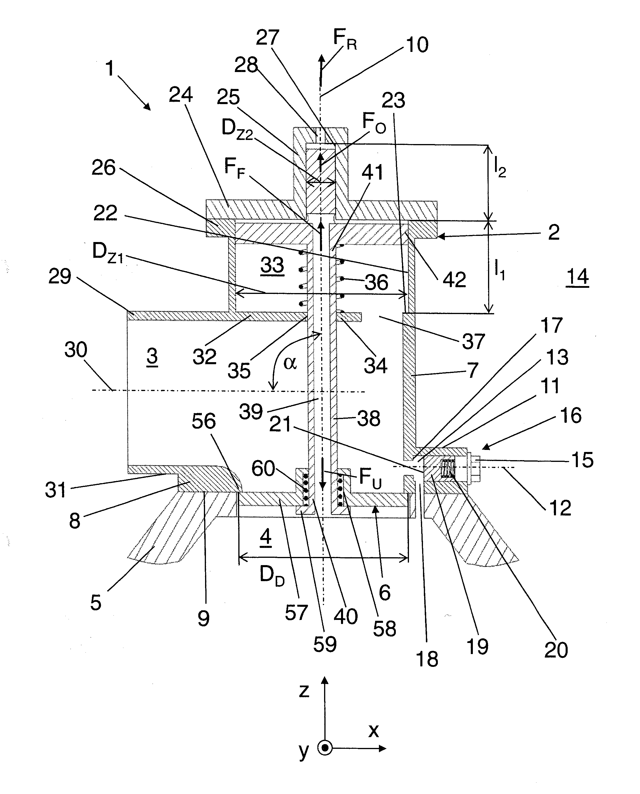
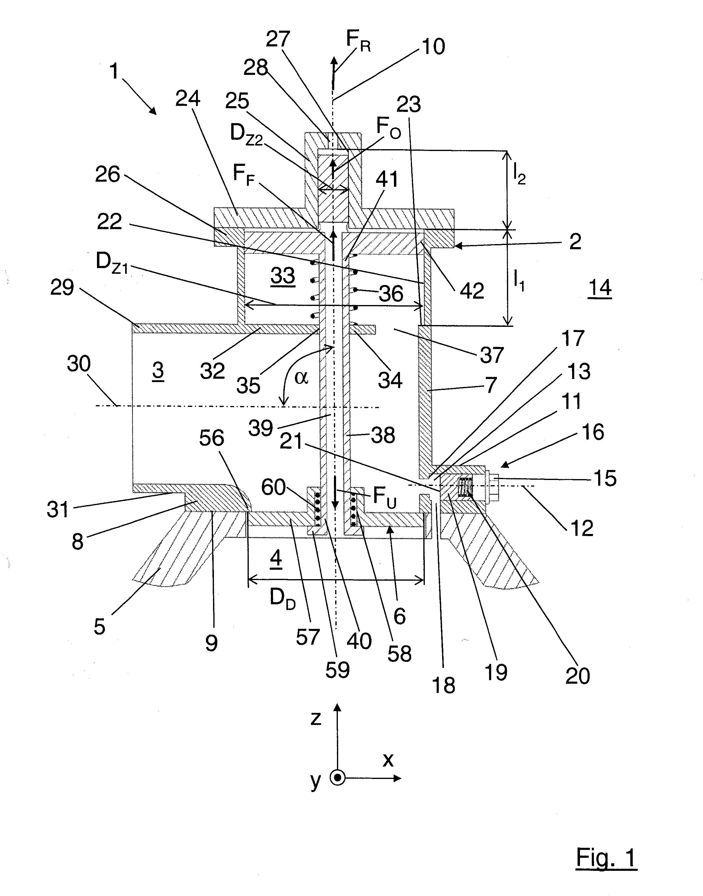
[0035]FIG. 1 shows a preferred embodiment of a gas inlet valve 1 for a compressor, in particular for a rotary compressor. For example, the compressor is designed as a screw-type compressor, sliding vane compressor, scroll compressor or the like, which is preferably driven by means of an electric motor or internal combustion engine. The compressor can for example be designed to be lubricated with fluid or to operate dry. The compressor preferably comprises a pressure space which is arranged downstream of a compressor block of the compressor. In a compressor lubricated with fluid, the pressure space can be designed as a fluid separation tank, in particular as an oil separation tank or as a water separation tank. In a compressor which operates dry, the pressure space can be designed for example as a portion of a pipe downstream of the first compressor stage. In the present case, the preferred embodiment of the gas inlet valve 1 will be described with reference to an oil-injected screw-...


PUM


Abstract

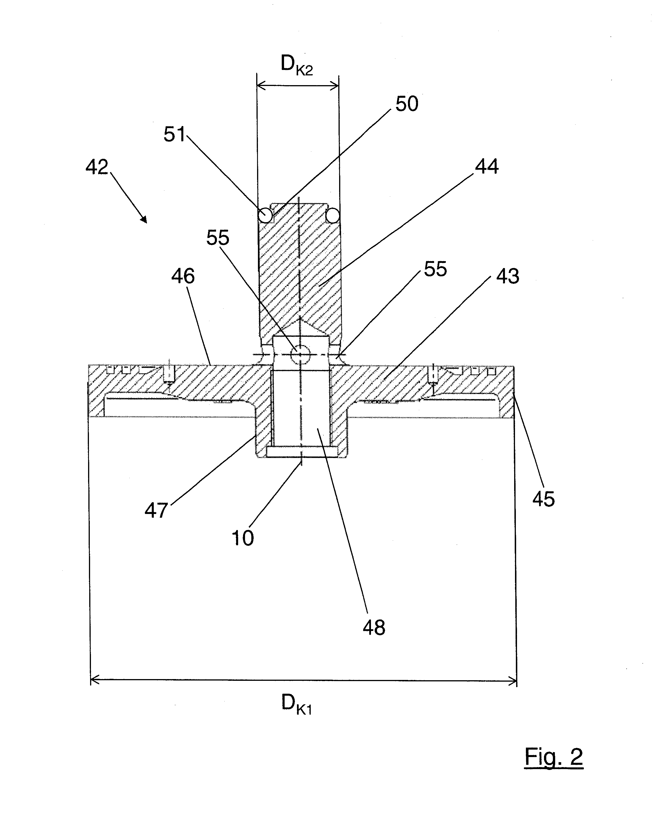
A gas inlet valve (1) for a compressor (64), comprising: a housing (2); a valve device (6) arranged between a gas inlet portion (3) and a gas outlet portion (4), a valve body (57) resting against a valve seat (56) in a sealing manner when the valve device (6) is in a closed operating state, and the valve body (57) being lifted from the valve seat (56) when the valve device (6) is in an open operating state; a piston device (42) which comprises a first piston portion (43) and a second piston portion (44) which is different from the first piston portion (43), the first piston portion (43) being displaceably guided in a first cylinder portion (22) of the housing (2) and the second piston portion (44) being displaceably guided in a second cylinder portion (27) of the housing (2) which is different from the first cylinder portion (22); and a piston rod (38) which is displaceably mounted in the housing (2) and mechanically couples the valve body (57) of the valve device (6) to the piston rod (38), a fluid line (39) putting a first cylinder chamber (49) of the first cylinder portion (22) in operative fluid communication with the gas outlet portion (4), it being possible to apply a control pressure to a second cylinder chamber (52) of the second cylinder portion (27) in order to lift the valve body (57) from the valve seat (56). A rotary compressor comprising a gas inlet valve (1) of this type and a method for operating a compressor (64), in particular a rotary compressor, comprising a gas inlet valve (1) of this type.

Description

FIELD OF THE INVENTION[0001]The present invention relates to a gas inlet valve for a compressor, in particular for a rotary compressor, to a compressor, in particular a rotary compressor, comprising a gas inlet valve of this type and to a method for operating a compressor, in particular a rotary compressor, comprising a gas inlet valve of this type.BACKGROUND OF THE INVENTION[0002]Although the present invention is applicable to any compressors, the present invention and the problem on which it is based will be described in detail in relation to a rotary compressor.[0003]A compressor is usually driven by a transducer in a directly coupled manner or via a gearing and compresses a medium, in particular a gas, preferably air, as soon as the compressor is set in movement. However, this mode of operation has some drawbacks with regard to establishing a compressed air network. In a modern industrial plant, compressed air is used for many different applications. Depending on the number of l...

Claims


Application Information

Patent Timeline
IPC IPC(8): F04C29/12
CPCF04C28/06F04C28/26F04C29/126F04C18/16F04C2270/58F04C29/124F04C28/24
Inventor FOERSTER, ANDREAS
Owner KAESER KOMPRESSOREN SE
Learn More