
Radio frequency receiver

Inactive Publication Date: 2013-05-30
ELECTRONICS & TELECOMM RES INST
View PDF9 Cites 10 Cited by
  • Summary
  • Abstract
  • Description
  • Claims
  • Application Information

AI Technical Summary

Benefits of technology

The present patent is about a new radio frequency receiver that can work with multiple bands in a MIMO system. The receiver is designed to have a simple structure and be easy to manufacture at a low cost. The technical effect of this patent is that it provides a more flexible and cost-effective solution for multi-band MIMO systems.

Problems solved by technology

Thus, front-end architectures of radio frequency receivers in the terminals tend to be complicated and expensive.
For Multi-Input Multi-Output (MIMO), in particular, the number of filters will increase in proportion to the number of antennas, and the front-ends will become more complicated in typical radio frequency receivers.
Using a TX canceler has limitations in that noise figure performance of a receiver is degraded, interference rejection performance changes according to group delay characteristics, and cross modulation distortion performance is degraded due to non-linearity.
Using bonding-wire also has limitations in that bonding wire properties change in an actual manufacturing process, thus failing to ensure uniform quality.
Using an on-chip filter with active inductors also has limitations in that noise figure is not better than passive inductors due to thermal noise generated by active devices, and active devices consume more power and their characteristics change more easily than passive inductors.
For systems such as CDMA that have a relatively narrow broad bandwidth (of 1.25 MHz, for example), typical SAW-less receivers can remove jamming signals to some degree because the duplex gap between a desired signal frequency and a jamming signal frequency is sufficiently greater than a signal bandwidth by about 40 times. However, in broadband systems such as LTE, typical SAW-less receivers cannot sufficiently remove jamming signals.

Method used


Image

  • Radio frequency receiver
  • Radio frequency receiver
  • Radio frequency receiver

Examples


Embodiment Construction

[0036]Foregoing general illustrations and following detailed descriptions are exemplified to provide an additional explanation of the claimed invention. The present invention may, however, be embodied in different forms and should not be construed as limited to the embodiments set forth herein. Rather, these embodiments are provided so that this disclosure will be thorough and complete, and will fully convey the scope of the present invention to those skilled in the art.

[0037]It will be understood that when an element is referred to in the detailed description as being included, this means that another element may be included. Furthermore, an embodiment described and exemplified herein includes a complementary embodiment thereof. Hereinafter, embodiments of the present invention will be described in detail with reference to the accompanying drawings.

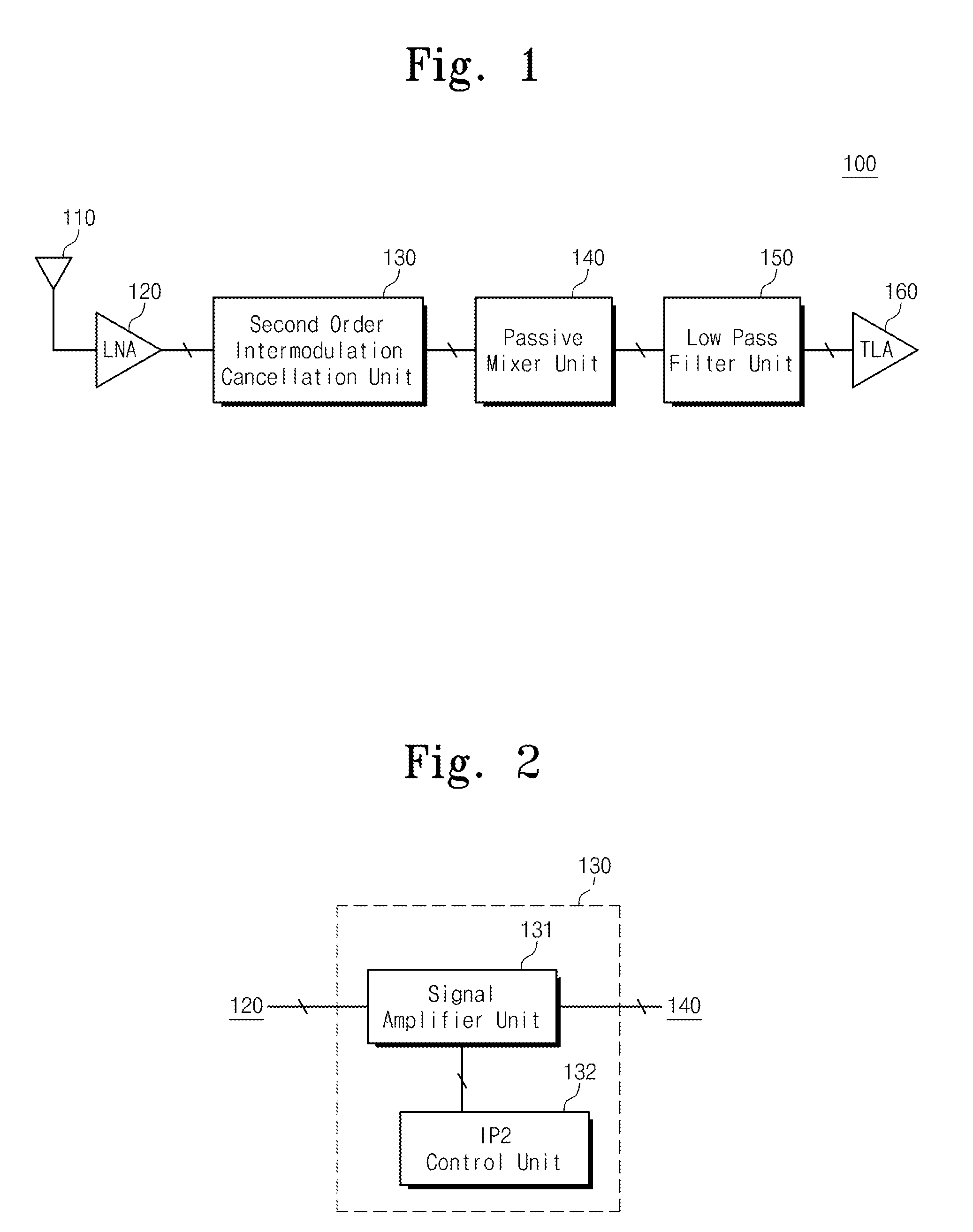
[0038]FIG. 1 is a view illustrating a radio frequency receiver 100 according to an embodiment of the present invention.

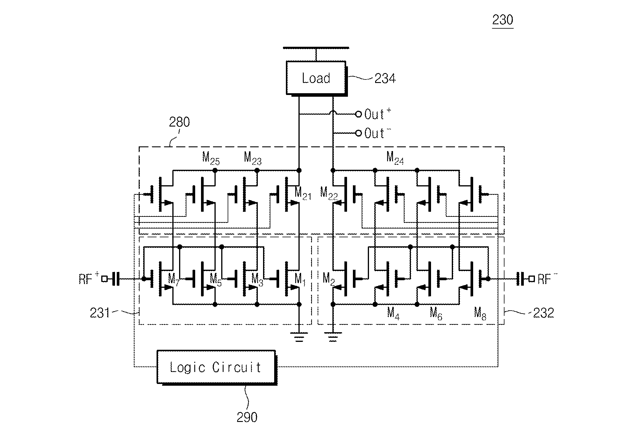
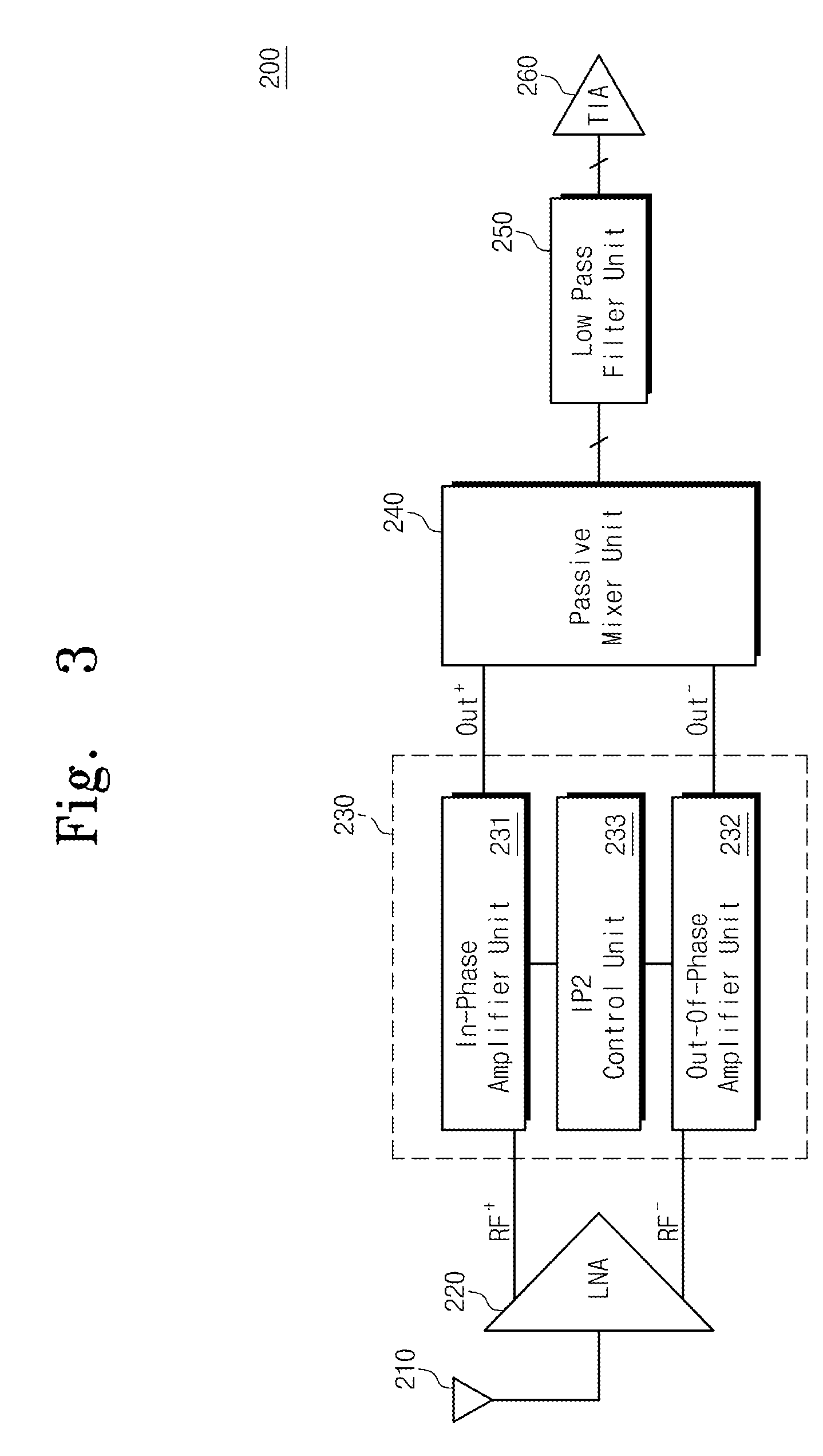
[0039]Referring ...


PUM


Abstract

A radio frequency receiver of the present invention removes out-of-band jamming signals and interference signals without SAW filters. The radio frequency receiver includes: a low noise amplifier amplifying a signal received through an antenna; a second order intermodulation cancellation unit removing second order intermodulation caused by an out-of-band jamming or interference signal included in the signal output from the low noise amplifier; a passive mixer unit converting a frequency of the signal output from the second order intermodulation cancellation unit; and a low pass filter unit removing an out-of-band jamming or interference signal included in the signal output from the passive mixer unit and delivering the signal with the out-of-band jamming or interference signal removed therefrom to a transimpedance amplifier.

Description

CROSS-REFERENCE TO RELATED APPLICATIONS[0001]This U.S. non-provisional patent application claims priority under 35 U.S.C. §119 of Korean Patent Application No. 10-2011-0124217, filed on Nov. 25, 2011, the entire contents of which are hereby incorporated by reference.BACKGROUND OF THE INVENTION[0002]The present invention disclosed herein relates to a radio frequency receiver, and more particularly, to a radio frequency receiver for removing out-of-band interference signals or jamming signals.[0003]To remove interference signals or jamming signals in frequency bands other than a specific band, Surface Acoustic Wave (SAW) filters are widely used in base stations or terminals in contemporary wireless communication systems.[0004]Terminals used in next-generation mobile communication such as LTE-Advanced should be capable of multi-band radio communication. Thus, front-end architectures of radio frequency receivers in the terminals tend to be complicated and expensive. For Multi-Input Mult...

Claims


Application Information

Patent Timeline
IPC IPC(8): H03F3/45H03F3/16
CPCH03F3/45179H03F3/72H03F2203/7236H03F2203/45302H03F2203/45394H03F2200/294H04B1/10
Inventor HYUN, SEOK-BONGPARK, BONG HYUKCHOI, YUN HOJUNG, JAE HO
Owner ELECTRONICS & TELECOMM RES INST
Learn More