
Power generation device and method

Inactive Publication Date: 2013-05-30
MIP
View PDF16 Cites 11 Cited by
  • Summary
  • Abstract
  • Description
  • Claims
  • Application Information

AI Technical Summary

Benefits of technology

This patent describes a method for generating electric power by using a working medium that is heated at one location and cooled at another. The working medium is circulated through an enclosed circuit, which drives a turbine and a generator to produce electricity. The velocity of the working medium is increased as it passes through the turbine, and a compression ring is used to prevent the flow near the rotational axis of the turbine. The method also involves insulating the enclosed circuit to mitigate heat loss and using a waste heat source to provide heat to the working medium.

Problems solved by technology

However, the large size and complexity of a commercial power plant also mean that such plants are very expensive, require long design and construction times, and are subject to regulatory scrutiny.
Such plants also use large amounts of water for cooling.

Method used


Image

  • Power generation device and method
  • Power generation device and method
  • Power generation device and method

Examples


Embodiment Construction

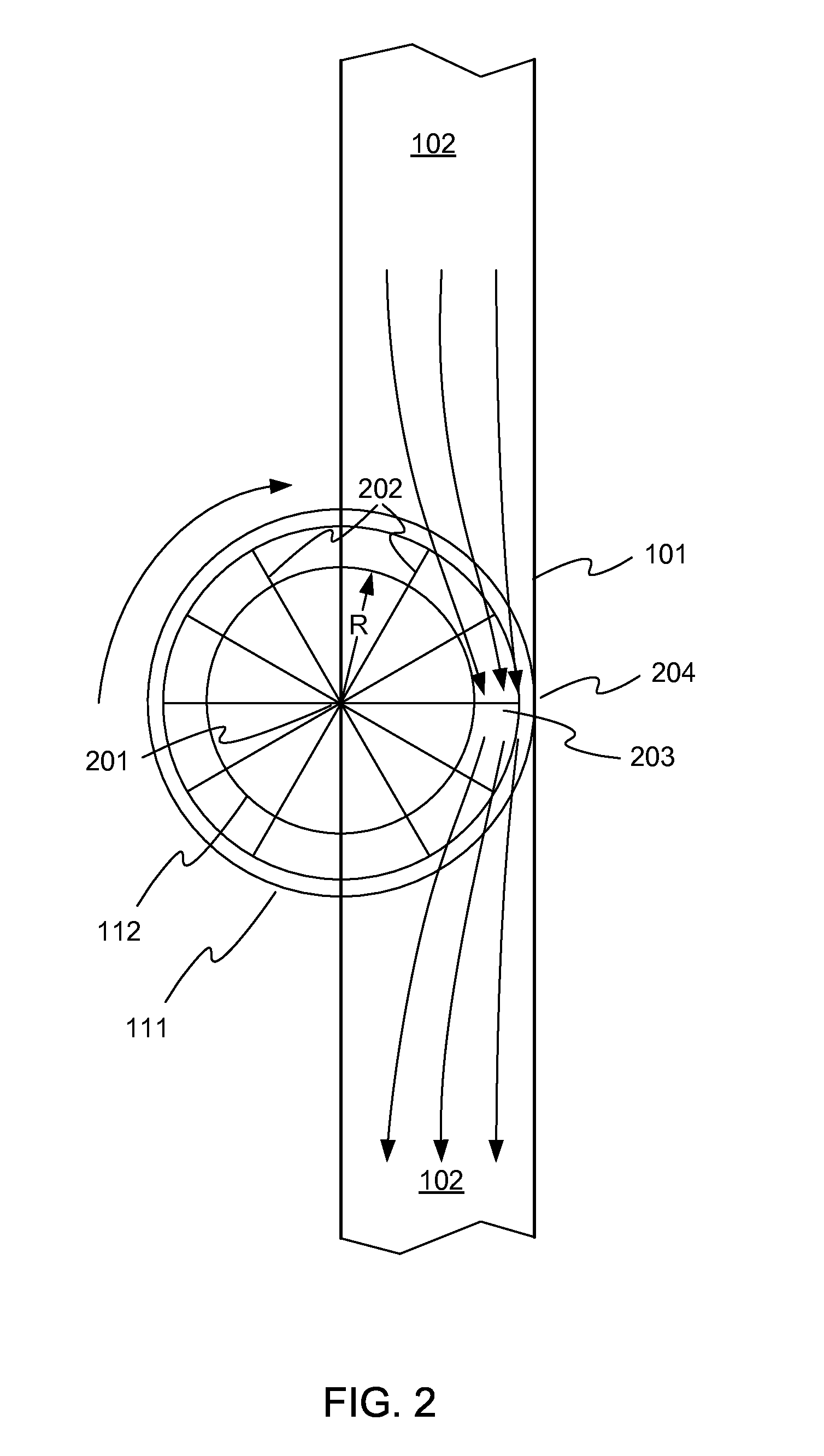
[0009]FIG. 1 illustrates a power generation device 100, in accordance with embodiments. Example power generation device 100 includes an enclosed tube 101, which is filled with a working medium 102. Working medium 102 may be, for example, a gas such as air, nitrogen, carbon dioxide, or another gas. For the purposes of illustration of this example, the working medium will be described as air, but it is to be understood that the claims are not so limited. The pressure inside tube 101 may be any suitable pressure, for example atmospheric pressure, or a pressure above or below atmospheric pressure. Tube 101 may be made of any suitable material, depending on its size, and on pressure and heat transfer requirements. Merely by way of example, tube 101 may be made of a metal such as steel or aluminum, of a polymer such as polyvinyl chloride (PVC), or a composite material. Different parts of tube 101 may be made of different materials.

[0010]Tube 101 may be sealed or substantially sealed at le...


PUM


Abstract

A power generation device includes an enclosed circuit through which a working medium circulates. The working medium is heated at a first location in the enclosed circuit, and cooled at a second location. The differential heating and cooling causes the working medium to circulate within the enclosed circuit. The circulating medium is used to drive a turbine, which in turn may drive an electric generator.

Description

[0001]This application claims priority from provisional U.S. patent application Ser. No. 61 / 491,686, filed May 31, 2011 and titled “Power Generation Device and Method”, the entire disclosure of which is hereby incorporated by reference herein for all purposes.BACKGROUND[0002]Most electric power is generated in large centralized power plants using fossil or nuclear fuel. Water is heated to make steam, which is then used to turn a turbine, which in turn drives an electric generator. Modern combined-cycle power plants can operate at thermal efficiencies as high as about 60 percent, and can generate large amounts of electric power.[0003]However, the large size and complexity of a commercial power plant also mean that such plants are very expensive, require long design and construction times, and are subject to regulatory scrutiny. Such plants also use large amounts of water for cooling. As the demand for power increases, and the world supply of fossil fuel is consumed, it is expected th...

Claims


Application Information

Patent Timeline
IPC IPC(8): F02G1/04
CPCF02G1/04F02C1/04Y02E10/72F03D9/00F05B2220/20F02C1/10F03D9/25
Inventor MCCALL, JOE
Owner MIP
Learn More