Coal material decomposition apparatus with combined screw-type bins

Inactive Publication Date: 2013-05-23
XIXIA LONGCHENG SPECIAL MATERIALS CO LTD
View PDF12 Cites 7 Cited by
  • Summary
  • Abstract
  • Description
  • Claims
  • Application Information

AI Technical Summary

Benefits of technology

[0005]To solve the above problems present in prior arts, an object of the present invention is to provide a coal material decomposition apparatus with combined screw-type bins, by which the pulverized coal can be separated rapidly with a heat exchange rate in a safe and convenient manner.
[0010]In this invention, a coal decomposition gas collecting pipe is arranged in the kiln body and provided with two parallel spirals for dividing space in the kiln body into a heating gas bin and a coal material decomposition bin isolated from each other. Therefore, a large amount of hot gas in the heating gas in brought into staggered contacts with the coal material decomposition bin through a helicoid, conducting and radiating the heat to the pulverized coal in the coal material decomposition bin, and the pulverized coal can fully absorb the heat so as to be heated for being decomposed into the gas, coal tar gas and coal with high heat-value in the coal material decomposition bin. The coal decomposition gas can be collected effectively and rapidly by the coal decomposition gas collecting pipe, and discharged out of the kiln body for use in subsequent process. By turning the kiln of the present invention to drive the two spirals, coal material in the coal material decomposition bin move forward. This spiral distribution in the kiln with high utilization increases the amount of feed and the rate of discharge. The division of the kiln space by the combined double spirals extends the path of the coal material moving in the high-temperature heating gas atmosphere, increases the contact area between the heating gas bin and the coal material decomposition bin, which achieve a more sufficient decomposition effect. Coal material in the kiln body is heated by heating gas in a form of gas circulation, which allows heat to be further taken sufficiently and reduce heat loss on the one hand, and reduces the exhaust emission on the other hand. Such decomposition apparatus for coal disclosed by the present invention makes the decomposition and separation of the pulverized coal more fast and efficient so as to save and fully utilize energy and greatly increase the utilization rate and level of coal resources, thus it will produce a significant economic and social benefits for the entire society.

Problems solved by technology

However, the above-mentioned technology is required to form pulverized coal into lumps or sift lump coal, which increases the cost of raw material, or result in the produced gas without a high heat value, a big additional value, and significant economic and social benefits.
This results in a significant resources wasting and environmental pollution.
Because the coal lumps on the clapboard are accumulated to a certain thickness, so they cannot be uniformly heated and decomposed, and are required to be cyclically heated and decomposed by the decomposed gas.
More importantly, since the presence of large amount of holes for ventilation and circulatory function provided on the clapboard, pulverized coal can leak through the holes.
Thus, it will increase the cost of pulverized coal decomposition, and reduce the economic benefits because the pulverized coal cannot be directly used for coal decomposition in up-draft kiln.
In practice, this process using close-packed pipes is very complex, and heat transfer effect is poor in that heat is transferred mainly by thermal radiation.
Additionally, the pipes for the propulsion of coal are also very complex when close-packed decomposition pipes are arranged in the kiln body and high-temperature heating bin is arranged outside the pipes.
In this way, the propulsive mechanism and the pipes can also not be easily connected in a hermetical manner, which causes heat exchange to be inadequate.

Method used


Image

  • Coal material decomposition apparatus with combined screw-type bins
  • Coal material decomposition apparatus with combined screw-type bins
  • Coal material decomposition apparatus with combined screw-type bins

Examples


embodiment 1

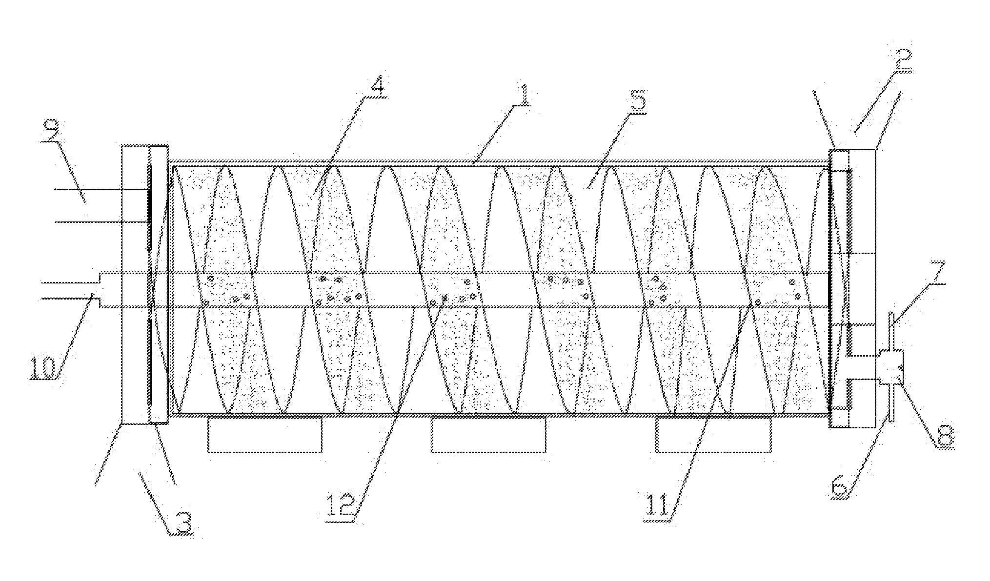
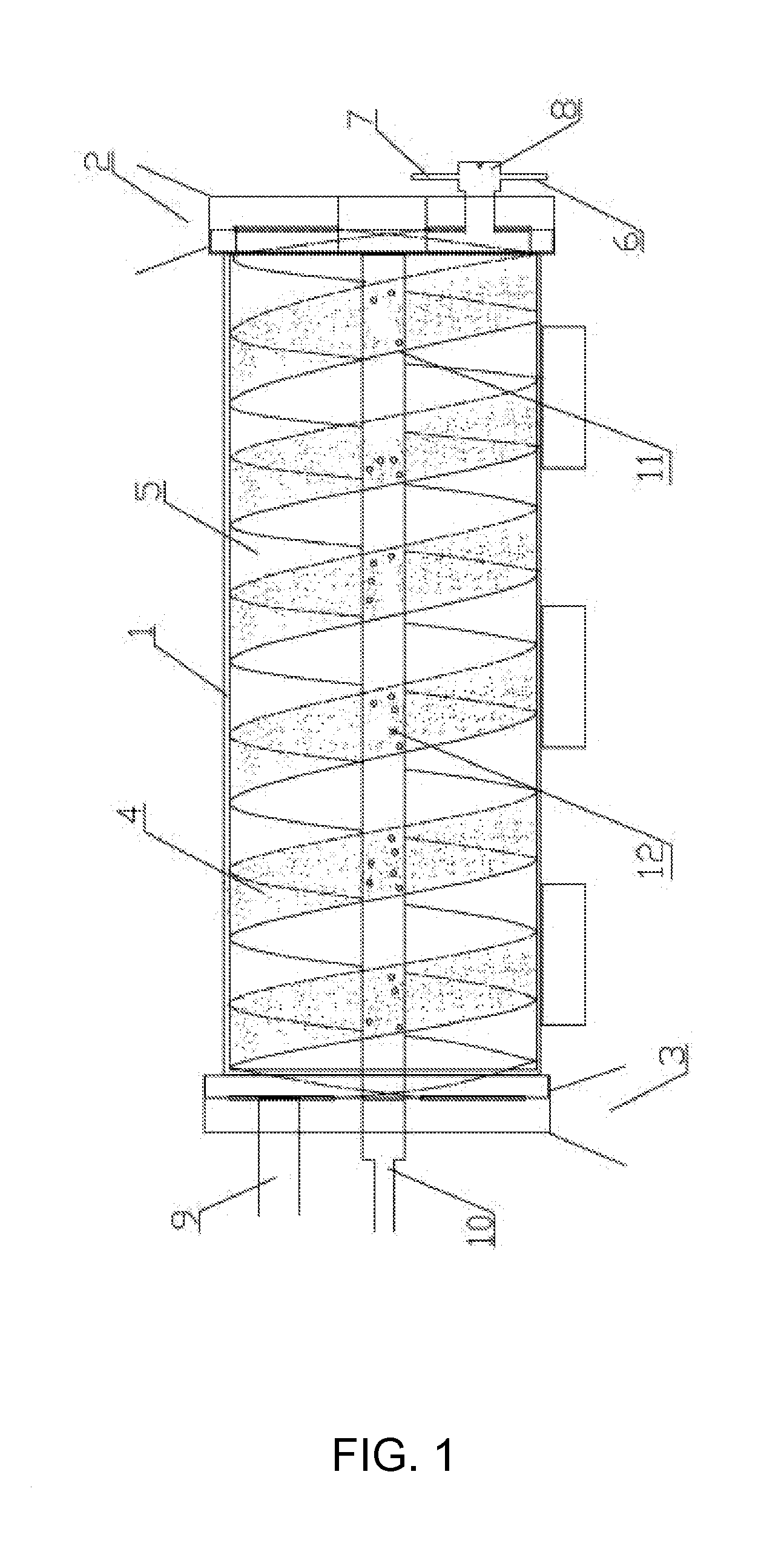
[0014]As shown in FIG. 1, a coal material decomposition apparatus with combined screw-type bins comprises a sealed rotary kiln body 1 provided with a coal inlet 2 and a coal outlet 3. A coal decomposition gas collecting pipe 10 is arranged in the kiln body 1. The coal decomposition gas collecting pipe 10 is provided with two parallel spirals 11. The internal edge of the spirals 11 is closely connected with the coal decomposition gas collecting pipe 10, and the external edge is closely connected with the inner wall of the kiln body 1. The two parallel spirals 11 divide the space in the kiln body 1 into a heating gas bin 5 and a coal material decomposition bin 4. The heating gas bin 5 is connected to a heating device and provided with a heating gas guide hole 9. The coal material decomposition bin 4 is connected to the coal inlet 2 and provided with a coal outlet 3 at the other end. The coal decomposition gas collecting pipe 10 is communicated with the coal material decomposition bin ...

embodiment 2

[0015]A coal material decomposition apparatus with combined screw-type bins comprises a sealed rotary kiln body 1 provided with a coal inlet 2 and a coal outlet 3. A coal decomposition gas collecting pipe 10 is arranged in the kiln body 1. The coal decomposition gas collecting pipe 10 is provided with two parallel spirals 11. The internal edge of the spirals 11 is closely connected with the coal decomposition gas collecting pipe 10, and the external edge is closely connected with the inner wall of the kiln body 1. The two parallel spirals 11 divide the space in the kiln body 1 into a heating gas bin 5 and a coal material decomposition bin 4. The heating gas bin 5 is connected to a heating device and provided with a heating gas guide hole 9. The coal material decomposition bin 4 is connected to the coal inlet 2 and provided with a coal outlet 3 at the other end. The coal decomposition gas collecting pipe 10 is communicated with the coal material decomposition bin 4 through a gas guid...


PUM


Abstract

A coal material decomposition apparatus includes a sealed rotary kiln body provided with a coal inlet and a coal outlet. A coal decomposition gas collecting pipe is arranged in the kiln body and is provided with two parallel spirals for dividing space in the kiln body into a heating gas bin and a coal material decomposition bin. The coal decomposition gas collecting pipe communicates with the coal material decomposition bin through a gas guide hole arranged in the coal material decomposition bin. As the kiln body is internally divided into the a heating gas bin and a coal material decomposition bin isolated from each other, a large amount of hot gas in the heating gas conducts and radiates the heat to pulverized coal in the coal material decomposition bin, and the pulverized coal fully absorbs the heat to be decomposed into gas, coal tar gas and coal with high heat-value.

Description

FIELD OF THE INVENTION[0001]The invention relates to comprehensive utilization of coal material for energy saving and emission reduction, particularly relates to a coal material decomposition apparatus with combined screw-type bins.BACKGROUND OF THE INVENTION[0002]In conventional technology, coal is used to produce coal gas, natural gas, or used to produce gas by coking at high temperature, medium temperature or low temperature. However, the above-mentioned technology is required to form pulverized coal into lumps or sift lump coal, which increases the cost of raw material, or result in the produced gas without a high heat value, a big additional value, and significant economic and social benefits. The heating mode of furnace can be classified as external-heating mode, internal-heating mode and hybrid-heating mode. The heating medium in external-heating furnace is not contact directly with raw materials and heat is transferred from furnace wall. The heating medium in the internal-he...

Claims


Application Information

Patent Timeline
IPC IPC(8): C10B7/10
CPCC10B47/44F27B7/34C10L9/08C10B7/10C10B1/10C10B47/30B01J8/087B01J8/10F28F5/06F28D7/026F28D11/02B01J2208/00212B01J2208/00407B01J2208/00415F27B7/20C10B53/04
Inventor ZHU, SHUCHENG
Owner XIXIA LONGCHENG SPECIAL MATERIALS CO LTD
Why Eureka
Try Eureka