
Power storage module

a power storage module and module technology, applied in the field of energy storage modules, can solve the problems of short cycle life, difficulty in being applied to such energy storage systems, and increasing the temperature of the whole module, and achieve the effect of uniform module temperatur

Active Publication Date: 2013-05-16
FDK CORP
View PDF4 Cites 44 Cited by
  • Summary
  • Abstract
  • Description
  • Claims
  • Application Information

AI Technical Summary

Benefits of technology

This invention describes an energy storage module that can control its temperature and prevent it from getting too hot or too cold, which can cause damage or premature failure. This allows for a consistent temperature and proper insulation for safety standards.

Problems solved by technology

Conventional types of lead batteries or other secondary batteries, which are not suitable for a high current charge-discharge and which have a short cycle life, have difficulties in being applied to such energy storage systems.
However, constant charging and discharging done with this type of energy storage module causes a single cell to generate heat, thus raising the temperature of the whole module.
Especially, when using an energy storage module having a structure encasing a plurality of single cells laminated therein, the heat inside the module will not easily be released, thereby causing the temperature of the module to rise, thus ephemeralizing or damaging the module.
Even if there is no such ephemeralization or damage, temperature unevenness within each module causes a difference in capacitance or internal resistance of each cell, thus totally disabling the module.

Method used


Image

  • Power storage module
  • Power storage module
  • Power storage module

Examples


Embodiment Construction

[0025]Hereinafter, Energy Storage Module 11 as the embodiment of this invention is described with reference to the drawings.

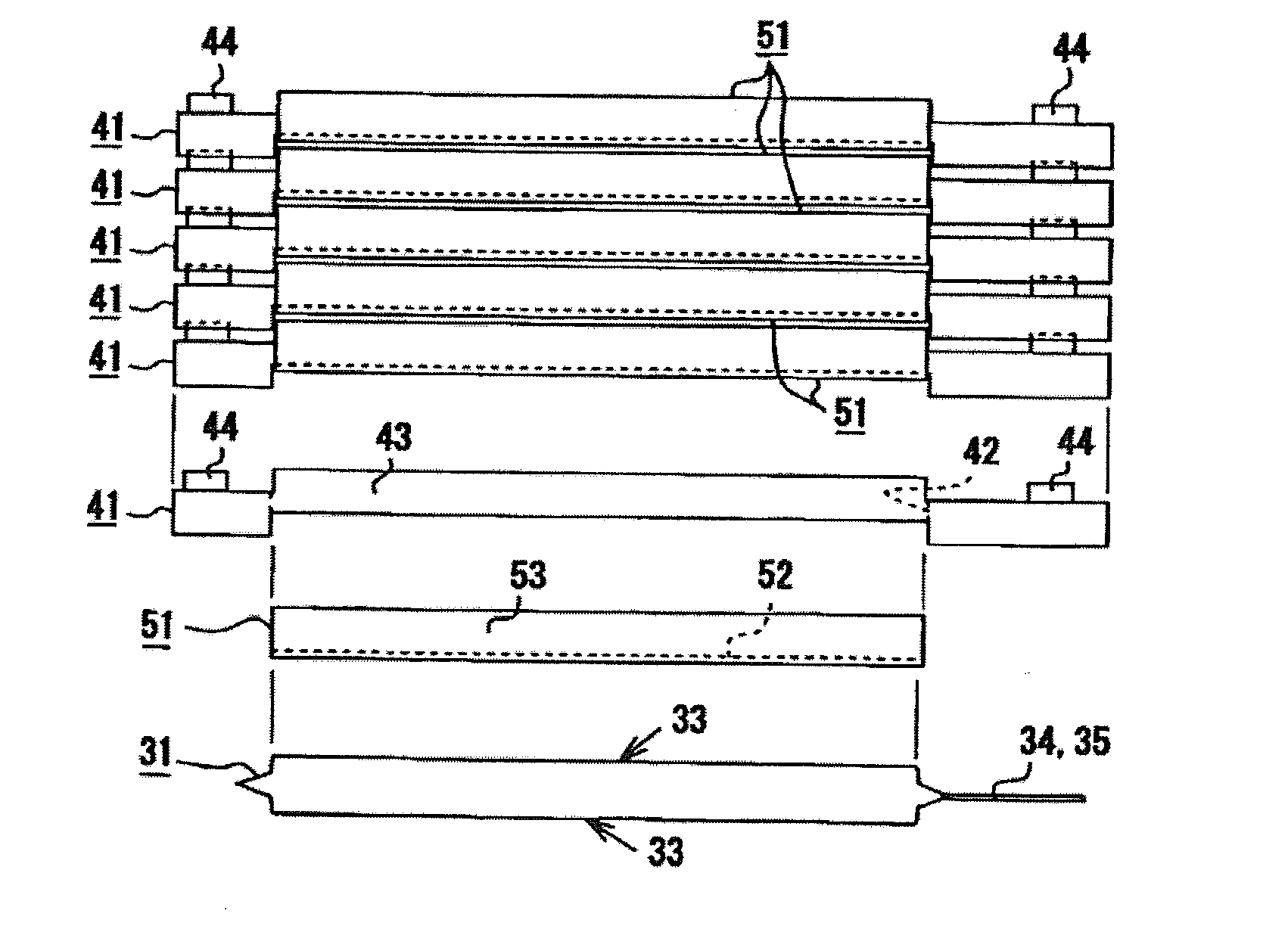
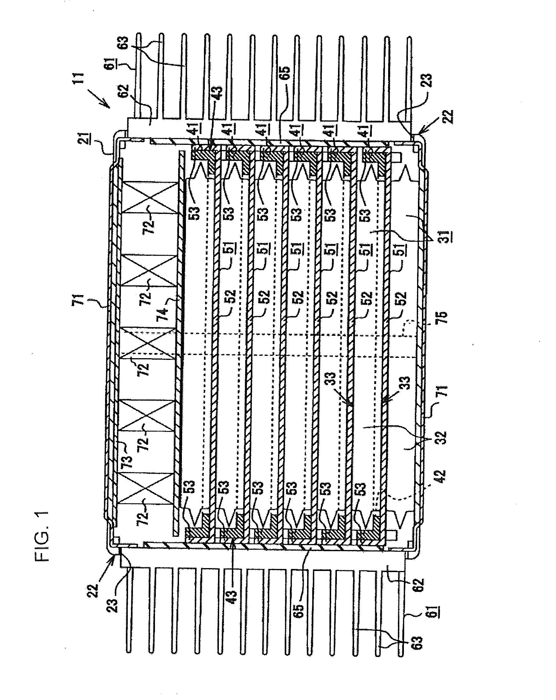
[0026]As shown in FIG. 1, the energy storage module 11 of the embodiment of this invention is a lithium-ion capacitor module having an insulation case 21 containing a fuel-cell stack structure containing therein a plurality of energy storage cells 31, a plurality of stacking plates 41 and a plurality of heat-transferring metal plates 51.

[0027]As shown in FIG. 4, an energy storage cell 31 is a lithium-ion capacitor cell comprising a polar laminated body having a laminated positive and negative electrode as well as separators and having plural units of laminated electric generating elements, with the positive and negative electrodes being oppositely located by a separator in each unit of the electric generating element.

[0028]The positive electrode is a structure made of materials reversely supporting the lithium ion formed on a positive current collector which su...


PUM

PropertyMeasurementUnit
angleaaaaaaaaaa
temperatureaaaaaaaaaa
capacitanceaaaaaaaaaa

Abstract

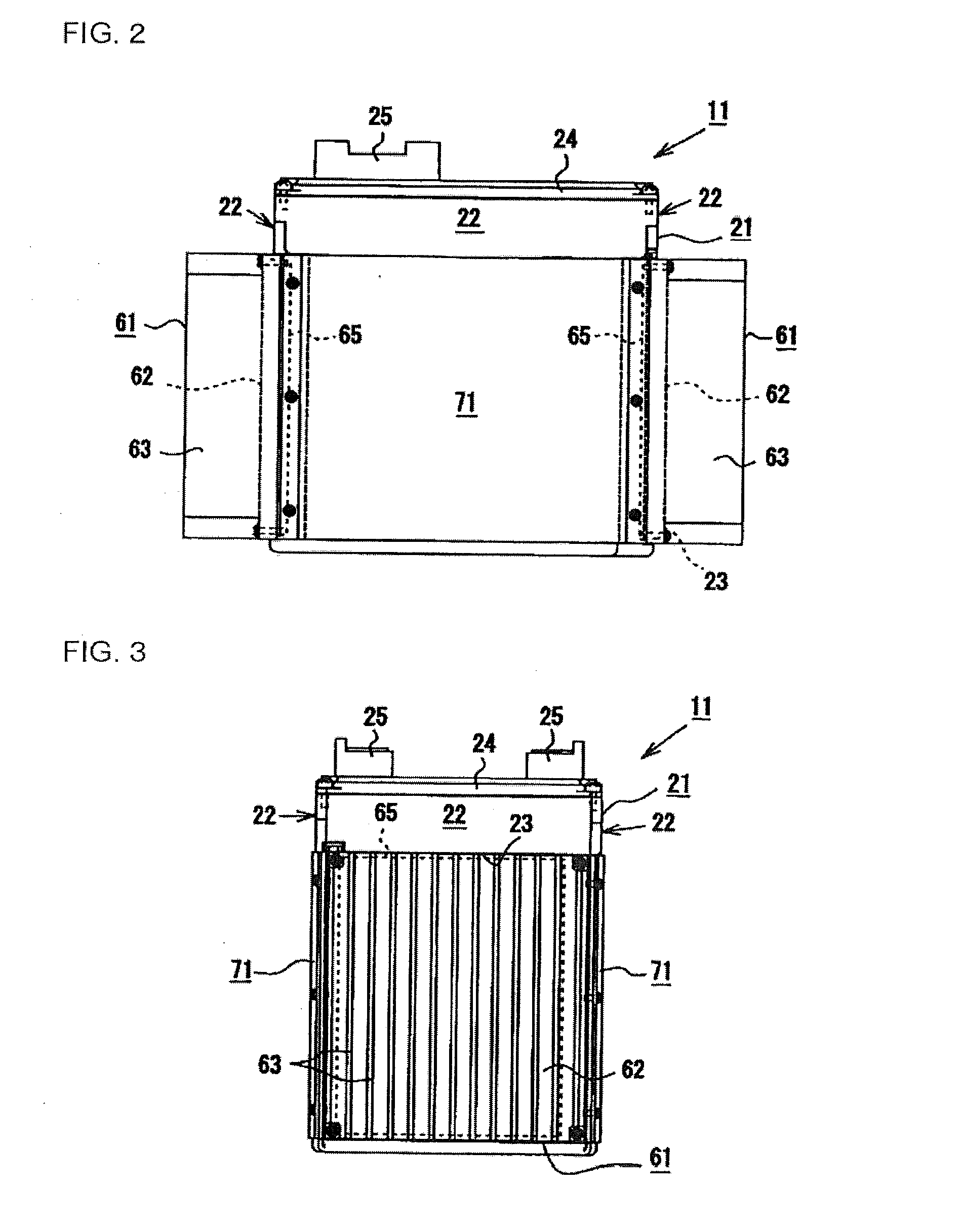
An energy storage module 11 comprises a case 21, a plurality of stacking plates 41, a heat-transferring metal plate 51 and a heat-releasing fin 61. An exposure outlet 23 is provided on the side 21 of the case 22 containing a plurality of energy storage cells 31. The stacking plate 41 having an aperture 42 is located between the plurality of energy storage cells 31 and is latched to another stacking plate 41 to position said plate. The heat-transferring metal plate 51 having a flat plate portion 52 and a bent portion 53 is provided in face-to-face contact with the main face 33 of each cell of the energy storage cells 31. The heat-releasing fin 61 projects from the exposure outlet 23 to the outside of the case 21 and is thermally face-to-face bonded to the bent portion 53 of the heat-transferring metal plate 51 by the insulation sheet 65.

Description

TECHNICAL FIELD[0001]This invention relates to an energy storage module comprising a structure in which a plurality of energy storage cells as well as power generating elements in an electrolyte solution are stored inside a metal laminated film material. Especially this invention relates to the aforementioned energy storage module characterized by having a heat dissipation structure and an insulation structure.BACKGROUND ART[0002]An energy storage device which can store a massive amount of energy and which can rapidly charge and discharge is required for electric load-leveling (load-control) equipment as well as solar-power generation, wind-power generation or the like and for momentary-voltage drop-prevention systems using electronic hardware such as computers or the like and for energy-regeneration systems or the like used in electric vehicles and hybrid cars. Conventional types of lead batteries or other secondary batteries, which are not suitable for a high current charge-discha...

Claims


Application Information

Patent Timeline
Patent Type & Authority Applications(United States)
IPC IPC(8): H01G9/00H01G11/00H01G2/08H01G11/06H01G11/10H01G11/18H01G11/78H01G11/82H01M2/10
CPCH01G9/155H01G11/06H01G11/12H01G11/18H01G11/82Y02E60/13H01M10/5004H01M10/5046H01M10/5055Y02T10/7022H01G9/0003H01M2/1077H01M10/6551H01M10/6555H01M10/613Y02T10/70Y02E60/10H01G2/08H01M50/20
Inventor WATANABE, KATSUHIKO
Owner FDK CORP
Learn More