
Adhesive composition and method for manufacturing a laminate using the adhesive composition

a technology of adhesive composition and composition, which is applied in the direction of film/foil adhesives, chemical/physical/physical-chemical processes, energy-based chemical/physical/physical processes, etc., can solve the problems of uneven brightness within the surface of liquid crystal panels, degradation of view angle characteristics, and difficulty in controlling the size of polarizing films, etc., to achieve easy peeling, increase the effect of irradiation amount of electromagnetic waves or particle beams, and easy peeling

Inactive Publication Date: 2013-05-16
NITTO DENKO CORP
View PDF4 Cites 3 Cited by
  • Summary
  • Abstract
  • Description
  • Claims
  • Application Information

AI Technical Summary

Benefits of technology

[0032]The present invention aims at providing adhesive composition and a method for manufacturing a laminate using the same, which allows for: preventing misalignment when laminating adherends; strongly bonding of the adherends when a correction of lamination is not required; and easily peeling the adherends without any damage thereto when a correction of lamination is required.Means to Solve the Problem
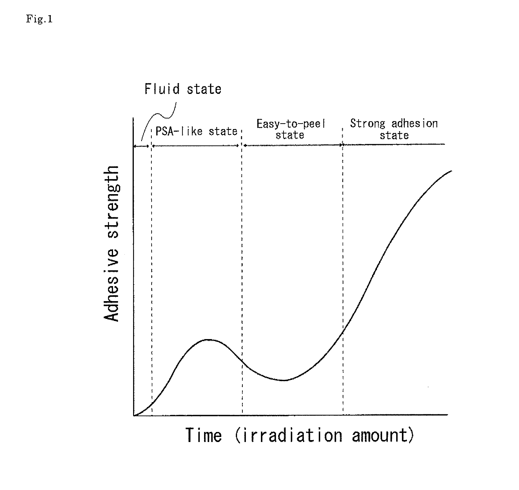
[0040]In the adhesive composition according to the present invention, increase of the irradiation intensity of the electromagnetic wave or particle beam and / or increase of the temperature reduces time necessary for the adhesive strength increasing to the local maximum value, decreasing from the local maximum value to the local minimum value, and increasing to a value greater than the local maximum value from the local minimum value. According to the present invention, appropriate selection of the irradiation intensity of the electromagnetic wave or particle beam and the temperature for bonding allows for arbitrarily controlling time for the adhesive composition reaching to a certain adhesive strength and state and controlling time to maintain the state. Thus, use of the adhesive composition according to the present invention allows for higher degree of freedom in process to laminate the adherends with the adhesive composition.

Problems solved by technology

Thus, it is difficult to control change of the size of the polarizing film in an environment where a size of a polarizing film changes by heating or moisturizing after laminating the polarizing film and a liquid-crystal cell via a PSA layer.
If the size of the polarizing film changes, it could cause unevenness in brightness within a surface of a liquid-crystal panel.
In addition, it could cause degradation of view angle characteristics in that a contrast is degraded when the liquid-crystal panel is viewed at an oblique angle.
These demerits may be further noticeable along with upsizing of liquid-crystal panels in coming days.
However, when a thin polarizing film is laminated with a liquid-crystal cell using a PSA, a change in size of the thin polarizing film due to heating, moisturizing or an abrupt temperature change may cause cracks therein.
Because of this, in a present liquid-crystal panel manufacturing technique using a PSA, a thin polarizing film having a protection film laminated only on one of the surfaces of a polarizer has not been put into practical use.
Thus, when a force is applied to a surface of a polarizing film, the polarizing film itself may be deformed even when a hard coat layer is laminated on the surface thereof because repulsive force of the PSA is weak, and a dent and / or a collapse may be generated on the surface of the polarizing film and / or the hard coat layer.
This problem may be particularly serious when using a thin polarizing film which seems to be promising in coming days.
However, since adhesion between the polarizing film and the liquid crystal cell via a PSA may be strong enough to maintain a liquid crystal panel as a product, a large force is required to actually peel the polarizing film from the liquid crystal cell.
But, applying a large force to peel the polarizing film from the liquid crystal cell may adversely affect the liquid crystal cells.
In such a case, removing process of the remaining polarizing film is complex.
In the technique, ultraviolet ray is irradiated to a degree not to fully cure the adhesive so that it is in a weak adhesion state.
If any abnormality such as misalignment of the polarizing film is found in the inspection, the adhesive is removed from the polarizing film except when the polarizing film itself is defective.

Method used


Image

  • Adhesive composition and method for manufacturing a laminate using the adhesive composition
  • Adhesive composition and method for manufacturing a laminate using the adhesive composition
  • Adhesive composition and method for manufacturing a laminate using the adhesive composition

Examples


example 1

[0133]One part of a photo-polymerization initiator (Irgacure819 from Ciba Japan K.K.) was added to 100 parts of N-(2-hydroxyethyl)acrylamide monomer (from Kohjin Co., Ltd.) and dissolved to prepare adhesive composition. To accelerate rate of dissolution, ultrasonic wave was applied while heating at 50° C. One milliliter of the adhesive composition was dropped onto a plate glass with a dropping pipette, a polarizing film (VEGQ5724DU from Nitto Denko Corporation) was overlapped thereon, and the polarizing film was pressed with a hand-roller to laminate the polarizing film and the plate glass. The thickness of the adhesive composition was adjusted to 10 μm. Glass transition temperature (Tg) of the adhesive composition was 98° C. The size of the plate glass was 150×50 mm and that of the polarizing film was 140×40 mm.

[0134]Since TAC which an ultraviolet absorber is added thereto is used for a protection film of the polarizing film, light with wavelength of 380 nm or less hardly transmits...

example 2

Measurement of Critical Irradiation Intensity

[0142]A half part of a photo-polymerization initiator (Irgacure819 from Ciba Japan K.K.) was added to 100 parts of N-(2-hydroxyethyl)acrylamide monomer (from Kohjin Co., Ltd.) and dissolved to prepare adhesive composition. To accelerate rate of dissolution, ultrasonic wave was applied while heating at 50° C. One milliliter of the adhesive composition was dropped onto a plate glass with a dropping pipette, a polarizing film (VEGQ5724DU from Nitto Denko Corporation) cut in sheets having a width of 25 mm was laminated therewith. The thickness of the adhesive composition was adjusted to 10 μm. The plate glass laminated with the polarizing film was placed in an oven heated to 40° C., and light was irradiated from the polarizing film side with an ultraviolet irradiator (UBX0801-01 from Eye Graphics Co., Ltd., a high voltage mercury lamp with output of 8 kW). For preventing the temperature of the polarizing film or the plate glass overheated tha...

example 3

Control of Adhesive Strength and State by Irradiation Intensity of Electromagnetic Wave or Particle Beam

[0145]For the same adhesive strength composition in Example 1, change of state of the adhesive composition depending on the irradiation time when varying the irradiation intensity was observed under the same conditions as Example 1 except the irradiation intensity of light. The irradiation intensity at the wavelength of 405 nm was varied in a range from 1.5 to 35 mW / cm2. The result is shown in FIG. 5, where a cross (x) shows that the adhesive composition was at fluid state, a triangle (A) shows that the adhesive composition was at PSA-like state, a circle (∘) shows that the adhesive composition was at easy-to-peel state, and a double circle (⊚) shows that the adhesive composition was at strong adhesion state. From FIG. 5, it is understood that time for the state of the adhesive composition changing to the PSA-like state, time to the easy-to-peel state and time to the strong adhesi...


PUM

PropertyMeasurementUnit
glass transition temperatureaaaaaaaaaa
adhesive strengthaaaaaaaaaa

Abstract

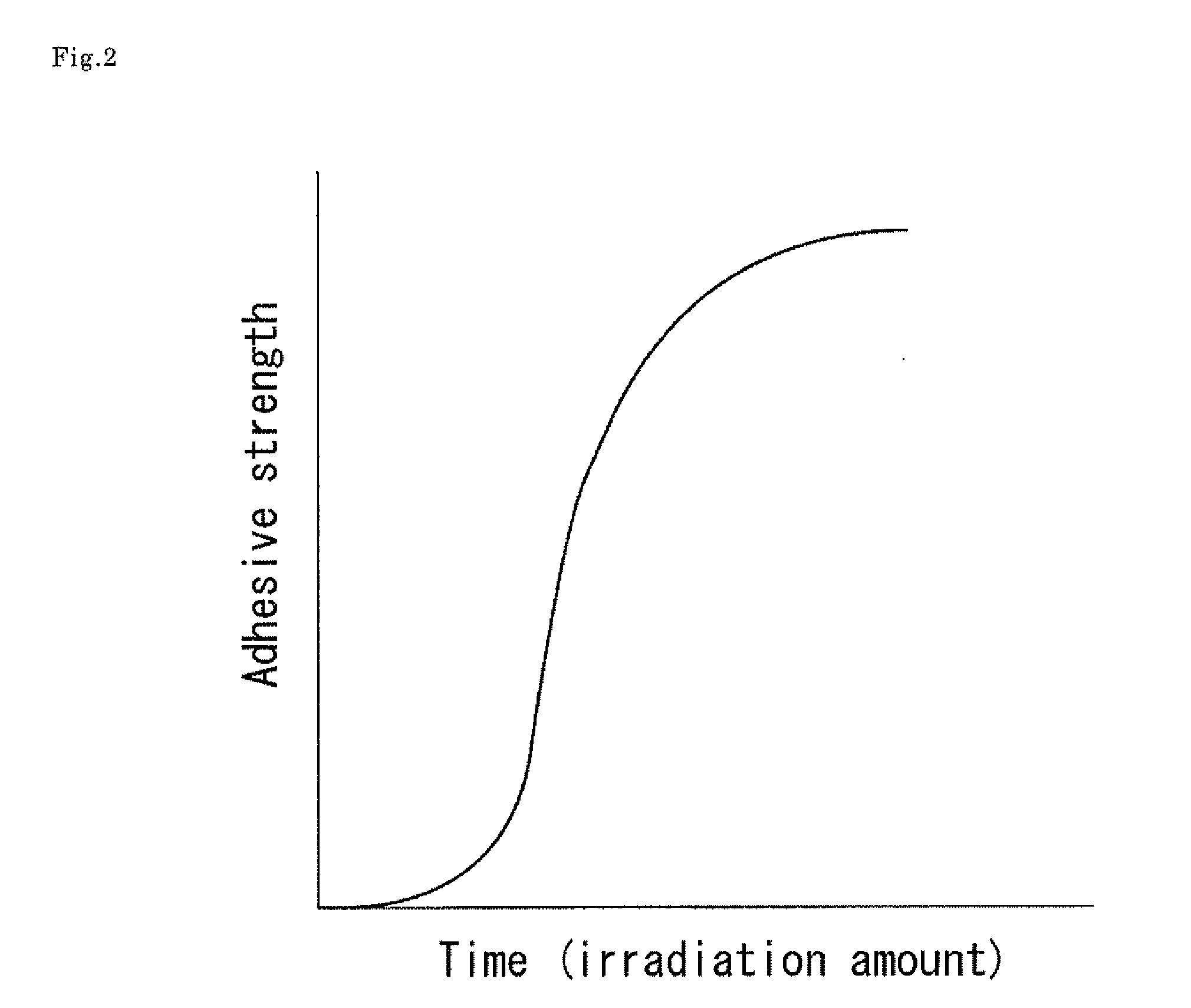
Adhesive composition according to the present invention includes an adhesive base agent consisting of a monomer and a polymerization initiator. Adhesion of the adhesive composition changes to take local maximum value, minimum value and a value greater than the local maximum value along with increase of irradiation amount of the electromagnetic wave or particle beam irradiated to the adhesive composition under a predetermined temperature environment. In a method for manufacturing a laminate according to the present invention allows for easy peeling of adherends and a layer of the adhesive composition when adhesion of the adhesive composition takes the minimum value.

Description

TECHNICAL FIELD[0001]The present invention relates to adhesive composition and a method for manufacturing a laminate using the adhesive composition. In particular, the present invention relates to adhesive composition and a method for manufacturing a laminate using the adhesive composition, for example used for mutually laminating two adherends, a substrate and a polarizing film, for manufacturing a liquid-crystal display unit, which develops adhesive strength by irradiation of electromagnetic wave or particle beam and allows for preventing misalignment when laminating and for peeling easily where necessary.[0002]A liquid-crystal display unit used for a liquid-crystal television is, in general, what a driving circuit, a printed circuit board for driving and, where necessary, a back-light are mounted on a liquid-crystal panel. The liquid-crystal panel is configured by laminating sheet-like polarizing films to both surfaces of a rectangular liquid-crystal cell which the configuration ...

Claims


Application Information

Patent Timeline
Patent Type & Authority Applications(United States)
IPC IPC(8): C09J4/00
CPCC09J4/00C09J133/02C09J133/20C09J5/00C09J137/00C09J139/04G02F1/133528C09J133/26C09J7/22C09J7/38C09J2203/318C09J2301/302G02B1/14G02B5/3025G02B5/305G02F1/1335G02F1/133509B32B38/0008B32B38/10C09J133/14C09J133/24
Inventor TAKEDA, KENTAROUOKAMOTO, MIKIMORI, TAKUYANAGATSUKA, TATSUKI
Owner NITTO DENKO CORP
Learn More